
Centrifugal pumps are mechanical devices that transport fluid from source to destination by increasing fluid pressure. During pump selection, the pump performance curve can be used to properly select a model and to evaluate the system performance.
Generally, the pump head decreases with the flow rate. Increasing the volumetric flow rate of the fluid increases the frictional losses of the system as the fluid travels inside the pipes, fittings, and valves from the source equipment to the pump and from the pump into the destination equipment. The frictional losses reduced the amount of the total head produced.
The pump performance curve or head capacity curve is developed empirically by testing the pump according to manufacturing standards. The resulting head and flow rate data gathered are adjusted to produce a smooth curve. The pump vendor/manufacturer may be requested to provide a performance curve for a single speed and impeller size, or multiple curves for a variety of impeller speeds or sizes. Figure 1 below shows a typical pump curve: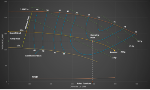
Figure 1. Pump curve showing efficiency over a range of impeller sizes.
Essentials found on the pump curve include:
Total Dynamic Head (TDH) or Pump Head is the energy that the pump has to impart to the liquid to transport it to the desired location. The head is the height in meters (m) or feet (ft) at which a pump can lift the fluid up. The pump head is independent of the fluid type, which means that the pump will raise the liquid to the same height regardless of its specific gravity.
Shut-Off Head is the pump head that occurs when the volumetric flow rate is zero which is achieved if the outlet of the pump is blocked-off while the pump is primed and running.
Rated Flow Rate is the volumetric flow rate or capacity at which the pump is designed. Rated flow rate usually includes a margin added to the normal flow rate e.g., 10%, 20%, and so on. The normal flow rate is determined in the process design and heat and material balance.
Run Out is the end of the pump manufacturer’s curve for the pump wherein maximum volumetric flow rate is attained.
Minimum Flow is the lowest volumetric flow rate at which the pump may be operated based on the pump vendor’s/manufacturer’s recommendations. Pump minimum flow is determined by the manufacturer by examining the temperature rise (minimum thermal flow), the minimum stable flow, the thrust capacity, the NPSH requirements, and the recirculation. The highest calculated flow rate using these elements is considered the minimum flow.
Pump Efficiency is the ratio of the actual power supplied to the liquid (water horsepower) to the power supplied to the pump from an outside source (electric horsepower). Pump efficiency for centrifugal pumps can be estimated from the specific speed and capacity of pumps.
Best Efficiency Point (BEP) is the volumetric flow rate on the pump curve where the efficiency reaches its maximum value for a given impeller diameter. Operating the pump near this condition will minimize power cost and pump wear.
Net Positive Suction Head Required (NPSHR) is designed by the pump vendor. The pump vendor determines the NPSHR for each pump over its complete operating range by a series of tests based on the industry standards. Industry practitioners have agreed on a 3% head loss at a specific capacity (constant flow) at the standard value to establish NPSHR.
Power or Brake horsepower (BHP) is the power required from the motor to drive the pump to deliver a given volumetric flow rate and head.
According to affinity law, centrifugal pump performance can be adjusted permanently by changing the rotational speed or the outside diameter of the impeller. A new pump performance curve is generated by adjusting the rotational speed or the outside diameter of the impeller as shown in Table 1.
Table 1. Affinity Laws
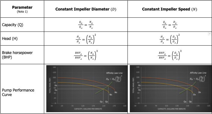
Note 1: The subscripts A and B refer to the original and adjusted conditions, respectively.
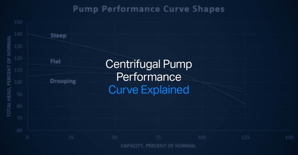
The impeller design influences the shape of pump performance curves. The pump performance curve shapes are steep, flat, and drooping. Figure 1 below shows these curves graphically.
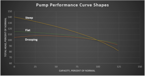
Figure 2. Pump Performance Curve Shapes
Steep Curve
In a steep centrifugal pump curve, the arch of the curve is steeper, resulting in a larger pressure (head) decrease as the flow increases, compared to a flat and drooping curve. This type of curve may be applied for systems that have large pressure/differential pressure requirements with minimal flow variation. A steep performance curve is preferred in process pumps such as reflux and feed pumps with at least a 10% head rise to shut-off ratio. The excellent stability of this curve is due to the steeper continuously rising shape.
Flat Curve
In a flat centrifugal pump curve, the arch of the curve is flatter, resulting in larger volumetric flow rate changes with little pressure (head) change. Centrifugal pumps with flat curves tend to suffer unstable operations if the frictional losses of the system are relatively small compared with the sum of static head and pressure head. In this case, the pump vendor/manufacturer must be consulted for the modification of the performance curve to match the system characteristics.
The pump vendor/manufacturer may suggest the installation of a restriction orifice at the pump discharge nozzle to restrict the flow of the fluid to achieve a steep curve rise to shut-off. Thus, altering the shape of the curve will give better controllability at the low flow region.
Drooping Curve
In a drooping centrifugal pump curve, it is possible to operate at either of the two volumetric flow rates at the same head. This type of curve is observed in centrifugal pumps with low volumetric flow rates, high-head, and operating at its optimum efficiency.
Pumps with a drooping curve to shut-off may fail to operate at either of two flow rates at the same head. When a pump with a not continuous rising curve to shut-off is used in a single operation, the volumetric flow rate must be in the range above the maximum head point. In parallel operation, pumps with drooping curves must not be used to avoid flow and pressure fluctuation.
Typical Pump Curve
When a specific pump curve from the manufacturer or other source is not available, typical pump curve can be used. The typical pump curve is defined as a second order polynomial:
y = Ax2 + B
The two coefficients, A and B, are determined from two known points:
Point 1: x1 = Rated flow rate, y1 = Rated Pump Head (RPH)
Point 2: x2 = 0, y2 = Shut-Off Head (SOH)
The shut-off head is calculated using the formula:
SOH=RPH (1+θ)
Where θ = Head Rise to Shut-off Ratio
A 0.25 to 0.30 head rise to shut-off ratio is a reasonable value for centrifugal pump calculations. Usually, the lower the value the flatter the curve. A head rise to shut-off ratio of zero results in a perfectly flat curve.
Understanding the pump performance curve and its elements can be used to properly select a pump, evaluate the system performance, and optimize the design.
