

Pumps installed in parallel can be found in many piping systems. The main purpose of installing or operating pumps in parallel is to allow a wider range of flow conditions than would be possible with the use of just a single fixed speed pump in systems which exhibit a widely varying flow demand. Examples of such applications include chilled water systems, process pumps installed in a variable capacity process, condensate pumps in steam power plant, wastewater or municipal water supplies etc.
When designing parallel pumping systems, the pumps should be selected to match each other and the system to ensure the pumps are always operating at a desirable or recommended duty-point on their respective capacity (Q-H) curves as well as ensuring the benefits of installing pumps in parallel are realised.
The following example as shown in Figure 1 will initially consider three identical pumps installed in parallel in a chilled water system. Each pump has the same operating speed and impeller diameter. The system includes two control valves which control a total system flow rate of 150 m3/h. In order to establish the operating conditions of the pumps and the system, a combined or composite pump chart will be developed. This composite pump chart will provide a clear illustration of the flow-head relationship for the pumps while operating in parallel.
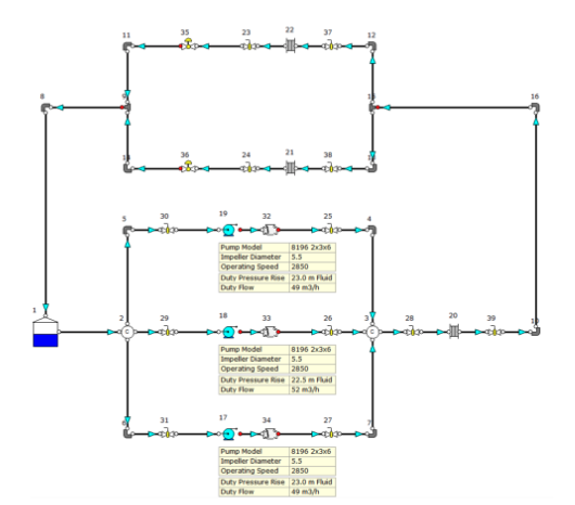
Figure 1: Chilled Water System with similar Pumps in Parallel.
The performance curves for the pump analysed in Figure 1 are provided in Figure 2. This figure illustrates the performance of just one of the pumps in the system.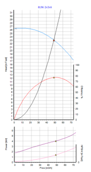
Figure 2: Performance Curves for the pump used in Figure 1.
A composite pump performance curve can be plotted for any given number of pumps in the system and in this case, the combined performance curve for all three pumps in operation has been developed as shown in Figure 3.
The capacity curve of the individual pumps is denoted by the dashed curve and the composite performance curve (representing all three pumps operating at the same time) is denoted by the solid blue curve. As all three pumps are identical, the capacity curve of the individual pumps overlap each other. This may become clearer in an example discussed a little later.
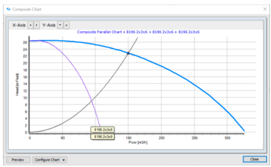
Figure 3: Composite Performance Curves for Similar Pumps in Parallel.
It can be seen from Figure 3 that the total flow through the system is represented by the intersection of the system head curve with the combined or composite pump curve plot i.e., at a flow rate duty-point of 150 m3/h.
In a lot of cases, the pumps installed in parallel may be dissimilar. Dissimilar pumps in parallel are often present in systems which have been expanded since the time of installation or in renovated or partially upgraded systems. Let’s consider changing one pump in the chilled water example in Figure 1. The pump labelled as node 19 in Figure 3 has been changed to Model No. 8196x1.5x3x6. The duty flow for the original pump was 49 m3/h whereas this new pump has a flow rate of 36 m3/h. As the total controlled flow rate in the system remains at 150 m3/h, the original remaining two pumps provide the 114 m3/h. Figure 4 provides an illustration of this system.
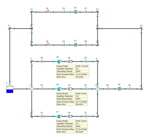 Figure 4: Chilled Water System with dissimilar Pumps in Parallel.
In Figure 3 we have seen that the combined performance curve had a smooth profile. However, when dissimilar pumps are operating in parallel, the performance curve is not smooth due to the way it is generated as the graphical sum of the individual pump curves. The combined performance curve for the three pumps in operation has been developed as shown in Figure 5.
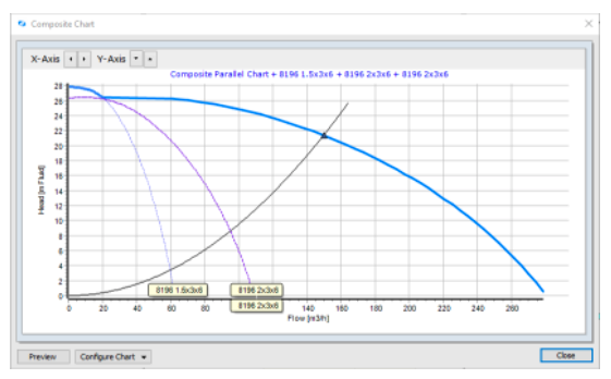
Figure 5: Composite Performance Curves for dissimilar Pumps in Parallel.
We can now see the performance curves for each individual pump model. The combined curve initially follows the curve for pump model 8196 1.5x3x6 because the maximum head for this pump is higher than that of pump model 8196 2x3x6. The combined curve then denotes the sum of the flow values at respective head values. The same principal applies as noted earlier i.e., the total flow of the three pumps is denoted by the intersection of the system curve with the combined curve.
When installing or operating pumps in parallel, it is generally agreed that the pumps should be identical. As outlined however, there may be scenarios where it is necessary to run dissimilar pumps in parallel. Another example of dissimilar pumps in parallel is where a pump impeller has been trimmed or where a pump impeller has been replaced with a larger impeller. Figure 6 is a continuation of Figure 4 however, the operating speed of pump impeller diameter for pump node 17 has been reduced rom 5.5 to 5.0 inches.
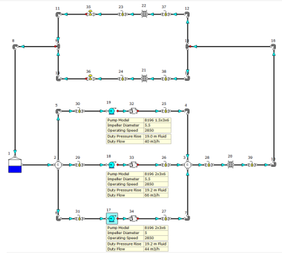
Figure 6: Chilled Water System with dissimilar Pumps in Parallel
(Impeller Diameter of Pump Node 17 Reduced).
Figure 7 provides an illustration of the combined performance curve for this scenario, and we can clearly see the performance curves for each individual pump model and the effect of the reduced impeller diameter on pump node 17 compared to that shown in Figure 5.
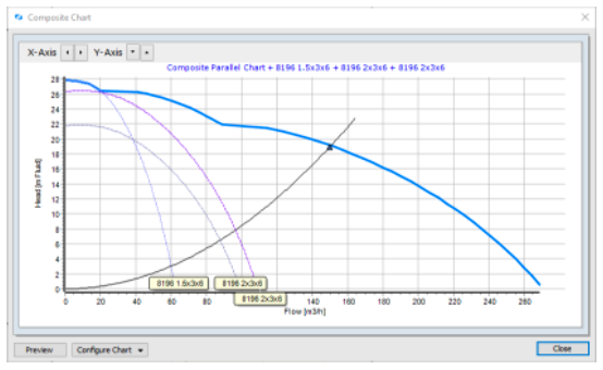
Figure 7: Composite Performance Curves for dissimilar Pumps in Parallel
(Impeller Diameter of Pump Node 17 Reduced).
There can be many reasons to install pumps in parallel. Pumps are sometimes installed in parallel to provide flow control i.e., cover a wide range of flow requirements for a system or process. They can also be installed in parallel to provide emergency backup or standby requirements. It’s often the case that when a system is undergoing expansion, new pumps are added to increase the system capacity. In these cases, the original pump model may no longer be available or dissimilar pumps may be required in parallel to achieve throughput. This can then become a complex design issue.
When pumps installed in parallel, they operate against the same discharge head and the combined/composite pump “Q-H” curve is determined by the sum of the respective flow rates of each pump at a series of head values. There are however many practical concerns, risks, factors and parameters that should also be considered.
If the pumps are not properly considered and selected for parallel operation, there may be resultant operating issues in the system. This can include general operational problems, pump damage, pump reliability issues, inefficient operation etc. An example case would be where mismatched pumps are installed in parallel and one of the pumps operates outside its intended operating range. This could be near the pump shut-off head and some way off the desirable pump BEP (Best Efficient Point). This can result in over-heating, seal damage, damage to the pump and ultimately, premature pump failure.
The ideal scenario when operating pumps in parallel is to have each pump operating in a desirable design region of their respective pump capacity curves. This will help ensure safe, effective and efficient operation whilst mitigating the risk of operational and maintenance issues.
When operating pumps in parallel, it’s always recommended to discuss with the pump Manufacturer or Vendor to help guarantee the trouble-free operation of the proposed pump model. It’s also important to discuss the topic of pump motor sizing for this intended operating scenario.
Composite pump curves can be developed in FluidFlow software for both parallel and series combinations.
References:
- Pumps & Systems.