
District Heating Systems provide a method of delivering thermal energy to buildings (homes and businesses) in the form of hot water through a distribution network of highly insulated pipelines. In this way, heat rather than fuel is delivered to buildings which are connected to the district heating system. As such, the buildings don’t require independent and dedicated heating plant meaning there is also no requirement for gas or oil deliveries to the buildings. A heat exchanger at each building transfers the heat energy from the district heating system network to the building’s own water-based heating system which in turn supplies heat for both space heating and domestic hot water requirements.
District heating systems have the ability to utilize and distribute heat from many different sources, including heat sources that are typically seen as a by-product and can usually go to waste, such as waste heat from electricity production and industry. To put that in some context, it has been estimated that there is enough heat currently going to waste from electricity production and large industries in Europe to meet all of Europe’s heating demands.
Once a district heating system is established, many heat sources can be connected to it. A great example system is the district heating system network in Aalborg, Denmark. This system is mainly supplied by waste heat from a large cement producer but also recycles waste heat from the local crematorium (Yikes!). The cement production processes require limestone and sand to be burned at high temperatures of around 1500oC. As a result, the Aalborg Portland cement facility has enormous supplies of excess heat. This excess heat has been harvested through heat exchangers etc and transferred into the Aalborg district heating system network.
In the case of the crematorium, the flue gasses are cooled from around 800 to 120oC and instead of emitting heat to atmosphere, the heat is harvested for use in the district heating system.
It has been quoted that the waste heat from the cement factory and crematorium can heat approximately 24,000 and around 20 to 25 regular Danish homes annually.
It has been quoted that the waste heat from the cement factory can heat approximately 24,000 homes and the waste heat from the crematorium can heat approximately 20 to 25 regular Danish homes annually.
As the main function of a crematorium and the cement factory is not to produce heat, the excess waste heat can be seen as a by-product of the respective processes.
High levels of recycled heat and renewable sources serve to lower the emissions from district heating systems as well as the cost of heat to the end consumer.
Germany is another good reference of a country utilising district heating systems. In 2018, it was said that approximately 14% of all households were connected to a district heating system. Hamburg stood out at the time as a front runner in district heating. The city had a vast district heating network supplying 19% of all households. This figure was to rise in 2020 by connecting an additional 50,000 households to the district heating network.
We have seen that District Heating Systems can facilitate the use of what could be considered waste heat. In addition to this, DH systems can also facilitate the use of renewable heat sources as well as combine heat and power (CHP) sources. DH technology has been undergoing a transition. Let’s look at a brief summary of the generations of district heating systems.
First Generation: This generation of district heating system was based on heat distribution by steam. This generation dates from around 1880 to 1930.
Second Generation: This generation of DH system was based on pressurised hot water with temperatures above 100oC (212 F). This generation dates from around 1930 to 1980.
Third Generation: This generation, like the Second Generation, was also based on pressurised hot water. This generation uses prefabricated, pre-insulated pipes which were buried in the ground and operate with temperatures below 100oC (212 F). This generation dates from around 1980 to 2010.
Fourth Generation: Sometimes referred to as 4th Generation, 4GDH this generation of DH system are designed to operate at lower temperatures (around 65oC (149 F)) and enable a more cost-effective method than that of using fossil fuels. The concept promotes the user of renewable and secondary heat sources such as that from groundwater or heat transfer from waste heat. The lower water distribution temperatures help limit installation costs and reduces ground heat losses. The ability to connect renewable heat sources whilst also harvesting of waste heat helps limit carbon emissions and reduce air pollution.
The development of DH systems over the years coincides with the advancement of higher insulation standards for buildings. This in turn reduces the heat demand on a DH system. This generation dates from around 2010 onwards.
Fifth Generation: The evolution of DH systems is to move toward water distribution networks which operate at near-ambient ground temperature conditions. This reduces heat losses to the ground whilst also reduces the overall insulation requirement. This system is then coupled with heat pumps in each connected building. The heat pump extracts heat from the DH system as needed. The same heat pump plant, when operating in reverse-cycle mode, rejects heat back into the DH network when the building requires cooling. This type of operating system permits heat to be shared among buildings from the same DH network. The fifth generation DH system allows efficient heating and cooling in city centres without contributing to air pollution and without emitting CO2.
Note, this offers a brief overview on the fifth generation DH system. Further reading is recommended on this topic for a better understanding of the more technical aspects of the system.
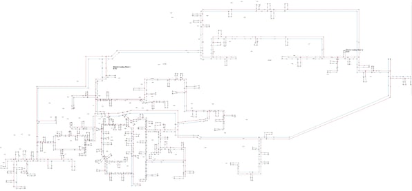
FluidFlow has been used to design and model district heating and cooling systems helping designers to understand operating conditions. Figure 1 gives an overview of a part-plan of a substantial district heating system and Figure 2 an overview of a district cooling system as modelled in FluidFlow.
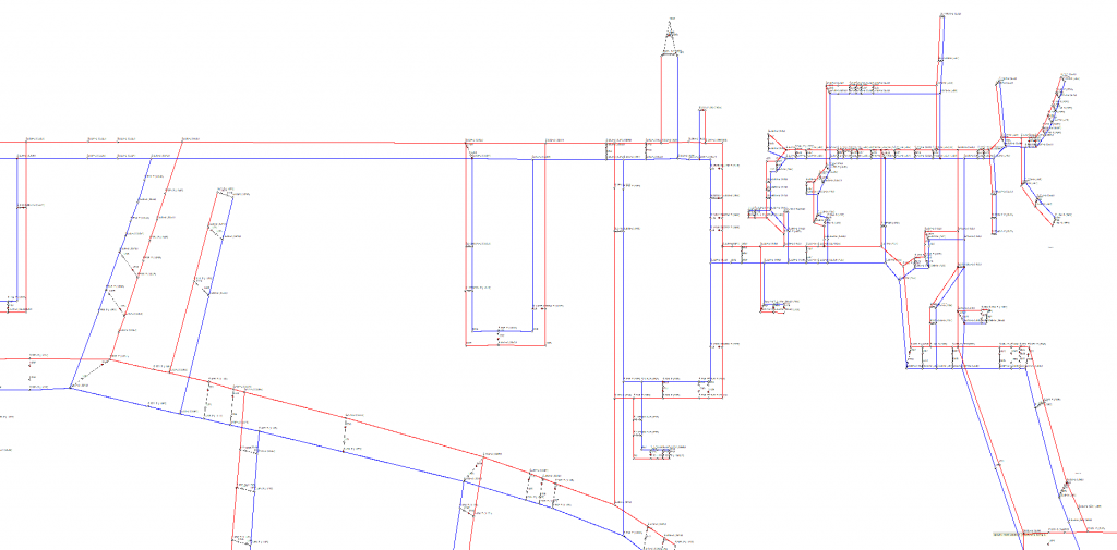
Figure 1: District Heating System (Part-Plan).
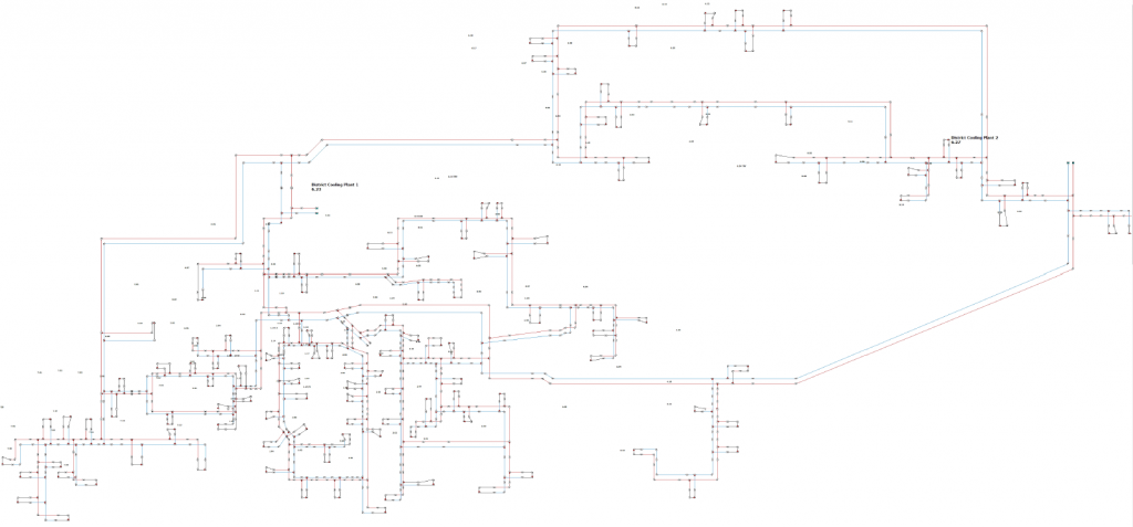
Figure 2: District Cooling Plant.
Using a suitable software tool, you can develop a model of the system and evaluate different operating conditions such as fluctuating user demand profiles. FluidFlow can perform such simulations and can be used to model and evaluate other operating scenarios for district heating systems. Take the following as an example case. You may for instance have an existing district heating system which is divided in two grids with each grid supplied from separate powerplant with dedicated pump stations. Each powerplant has two sets of pumps with heat exchangers between them. During the summer period when the flow rate is low (only sanitary water is to be heated) the whole district heating network can be supplied from just one powerplant. It may however be necessary to analyse the complete grid in such operation but with heating included thus with an increased flow.
Perhaps the system you wish to evaluate is an existing system and you wish to establish potential bottleneck issues through system expansion. A bottleneck can arise when pipes are too small to sufficiently meet end-user needs. This can result in insufficient differential pressure in district heating zones attached to these pipes. Bottlenecks are common in expanding district heating networks as what were previously sufficient pipe diameters become too small as more and more district heating consumers are connected in the network.
Bottlenecks have in the past been overcome by raising the initial temperature or the initial differential pressure. This however can lead to higher costs and higher heat losses (in the increased temperature scenario). In an attempt to avoid this, replacement of pipes for larger diameter pipes is considered as this increases the flow area reducing the velocity.
There are other techniques available to help resolve bottleneck problems some of which have included adding a heat source to the downstream side of the bottleneck or installation of thermal energy storage. Modelling systems with a suitable software tool can help greatly in identifying system short comings or potential short comings with future system expansion. A key point here is that the modelling of DH systems can help prevent bottleneck conditions in new or existing systems being expanded.
If bottlenecks are eliminated, it may be possible to further optimise the system by lowering the supply temperature or reduce the pumping power in the network. This would lead to benefits including lower heat losses and lower pumping power required.
Another scenario which may result in the occurrence of bottlenecks in DH systems is the transition towards 4th generation of DH systems as these systems are characterised by lower supply and return temperatures than the older more conventional DH temperatures. Lower supply temperatures in DH networks have been proven to exhibit a lot of advantages such as lower heat losses and more straightforward introduction of renewable or waste heat sources. However, lower supply temperature can also introduce some difficulties. The temperature difference in 4th generation systems is around 30oC which is lower than the normal temperature difference of around 40oC in the third-generation systems. Implementing or transitioning from third to fourth generation in an existing system would lead to higher flow rates. This increases the risk of bottlenecks. The same applies to lowering the supply temperature without lowering the corresponding return temperature.
To avoid too high flow rates in the pipelines, it is therefore important that the cooling among consumers is functioning well and efficiently and the pumping operation is well optimised.
Research has been completed on the different approaches or techniques which can and have in the past been applied to resolve bottleneck issues. The measures were classified into three groups: 1) Increased Distribution Capacity, 2) Local Supply and 3) Consumer Flow Management.
Increased Distribution Capacity
Supply Temperature: The approach of increasing the supply temperature can achieve positive results for simplicity and reliability with little or no investment costs. This is however a potentially costly option if it’s not used in small networks and for short time periods. This approach can result in increased heat losses and reduced efficiency in certain production units which therefore can produce a negative environmental outcome. The maintenance requirement can also increase as a result of higher potential for leaks as well as higher wear on pipes. This of course does depend on how often the supply temperature is increased and for how long. Multiple increases and decreases of the supply temperature can cause more wear on pipes than occasional or less frequent increases and decreases.
Larger Pipe Area: Although increasing the pipe diameter can improve operating conditions and reliability, it can be complicated by the requirement to excavate and replace existing pipes. This of course can exhibit a considerable investment cost.
Pumps: The pumps deliver pressure in the DH network and can be used to increase pressure at bottlenecks. Increasing the pump work with an existing pump can produce additional electricity demand with an unfavourable environmental outcome. Different pumping scenarios can be considered in a model, for instance, optimizing or modelling the capacity of the existing pumps, modelling replacement pumps in a system or analysing the effect of having distributed variable speed pumps as opposed to more centralised pump installation. There is evidence to indicate significant electrical energy savings can be achieved by using the latter approach.
Local Supply
Local heat Supply: This option consists of the addition of a local heat supply into the DH network downstream of the bottleneck. This can be a costly option. This approach does mean less heat and less flow is needed to be transported through the bottleneck location. Consideration also needs to be given to the ongoing future maintenance requirement and cost of connecting a new local supply.
The addition of a thermal store can also be used to avoid bottleneck problems. Accumulators can be loaded when the DH demand is low and unloaded when demand is high.
Consumer Flow or Demand-Side Management
At times with large heat demand (mornings and evenings), the space heating in buildings in areas with bottleneck problems may be controlled or kept to a certain threshold value without reducing the quality of service provided to the customers. The intention is to avoid the usage of top load production sources and to reduce energy consumption.
Note, this discussion simply gives a brief overview of available options to resolve bottleneck conditions. Further reading is recommended on the subject as there is a vast amount of information available on the topic.