
This blog gives a general outline of the rules or laws which can be used to predict fan performance in a given system. Why are the fan laws important? As an example, let’s consider the fan curve typically provided by a manufacturer. This fan curve is usually measured at “standard” or other stated conditions. In real systems, it is unlikely that a fan will be spending its operating life at these identical conditions. Furthermore, suction pressure variations, density changes, composition changes, etc are common and can also affect how the fan will operate in the system.
The fan laws help us estimate how a fan will operate in a system at different speeds, fluid density, impeller diameter, etc. Once we have a basic understanding of these laws, the performance of a fan can be calculated for various conditions.
The performance of geometrically similar fans of different sizes or speeds can be predicted with reasonable accuracy for practical purposes using the fan laws. A higher level of accuracy would require the effects of say, the viscosity of the gas, surface roughness of the fan, scale effect also be considered. However, depending on the level of accuracy required, for many fan calculations, this may not be necessary.
One point to note is that the laws apply to the same point of operation on the fan curve. They cannot be used to predict other points on the fan’s curve. The fundamental fan laws governing fan performance are generally only valid for a fixed system with no changes in airflow characteristics in the system or changes in aerodynamics. The term “system” refers to the combination of ducting, filters, grilles, dampers louvres, hoods, etc through which air is distributed.
As we know, the movement of air through a system causes friction/resistance between the air molecules and their surroundings and any other air molecules. Energy is therefore required to overcome this resistance. The faster the air moves through the system the greater the resistance imposed to flow and the more energy required to deliver the air through the system. This energy is described in terms of pressure. In general, the pressure required to overcome the resistance is referred to as static pressure. The pressure that results in the air/gas velocity is described as velocity pressure and the combination of these two values is often referred to as total pressure.
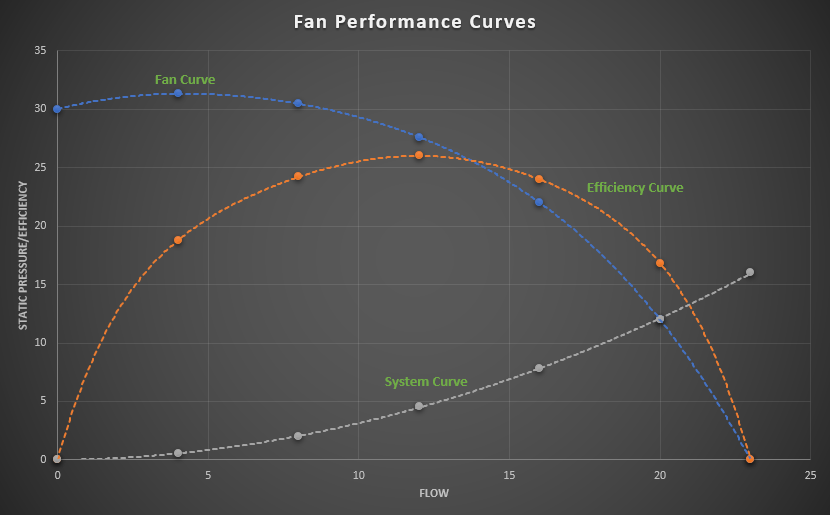
Fans or blowers are often installed in the ventilation or industrial process systems to overcome the resistance. Fan performance is often represented in the form of fan curves. The curves are based on a specific set of conditions which typically include speed, volume, efficiency, static pressure and power required to drive the fan at the given set of conditions. Figure 1 provides a typical illustration of fan curves. The point where the static pressure curve intersects the system resistance curve represents the duty-point for the fan.
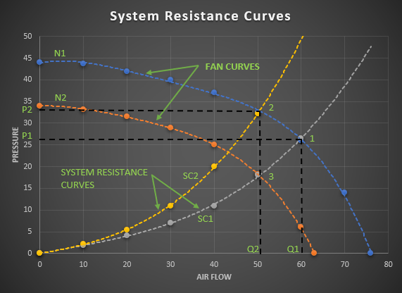
As noted earlier, as the airflow is increased in any fan system, the system resistance also increases. In a fixed system, it is said that the pressure required/system resistance varies with the square of the volume of air flowing through the system. The system resistance curve can be developed by determining the pressure required over a range of system flow rates. This resistance curve can then be plotted on the fan performance curve (also known as the fan capacity curve) to identify the actual duty-point. This is shown as point “1” in Figure 2 where the fan curve N1 and system resistance curve SC1 intersect. This duty-point is at airflow Q1 which is delivered against pressure P1.

Fans operate along a performance curve as provided by a manufacturer for a given fan speed. If we wish to reduce the air flow in the system, we could for instance partially close off a damper in the system or reduce the fan speed. Partially closing a damper will result in a new system resistance curve. This is shown as system resistance curve SC2 where the required pressure increases for any given air flow. The fan will now operate at duty-point 2 to provide the reduced air flow Q2 against the higher pressure P2.
On the other hand, we can reduce the fan speed from say N1 to N2 to reduce the airflow in the system and keep the damper in the fully open position. Under these conditions, the fan will now operate at duty-point 3 to provide the same airflow rate Q2 but at a lower pressure.
Therefore, reducing the fan speed is a much more energy-efficient approach to reduce airflow since less power will be required resulting in less energy consumption.
Fan Laws
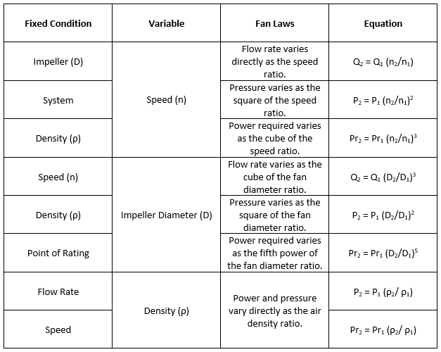
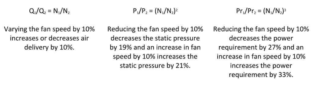
In general, the fan laws are typically used to calculate changes in flow rate, pressure and power of a fan when the size, speed or gas density is changed. In the fan laws outlined in Table 1 below, the subscript 1 represents the initial existing condition and subscript 2 represents the desired calculated condition.
The fan laws are a group of equations used to determine the effects of changes in the fan operating speed, the fan diameter or the density of the air in the system. The performance of a centrifugal fan, axial fan or blower is often given as a series of pressure, efficiency and shaft power characteristic curves plotted against air flow rate for specified values of speed, air density, and fan dimensions. It is, therefore, useful to determine the operating characteristic of the fan at other speeds and air densities. Using the fan law relationships, families of fan curves can be developed for operating the fan at different speeds, etc.
The fan laws can also be utilized to consider test results obtained from smaller prototype fans to predict the performance of larger fans which are of course geometrically similar.
Knowing the performance of a given fan under set specified operating conditions, variations in the performance can be predicted according to the fan laws. It should be noted however that adding or removing components of a fixed system such as dampers or incurring density changes will create an entirely different system resistance curve. Also, it’s worth noting that changing fan accessories such as inlet dampers, inlet boxes will change the fan performance curve from the standard. This should, therefore, be considered before considering or applying the fan laws.
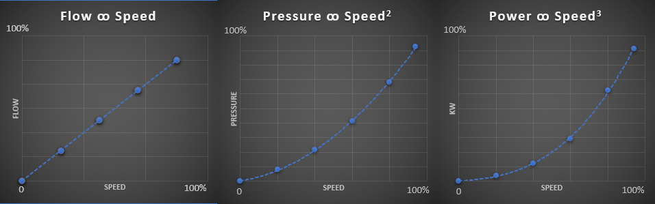
As part of the system design, the fan laws can be quite useful in determining alternate performance criteria or in establishing a minimum and maximum range. In the event that “safety factors” have been applied to system design calculations, it is worth noting that, based on the fan laws, a 10% increase in volume will result in a 33% increase in power requirement. Due consideration is therefore recommended on evaluating any applied “safety factors” against the actual cost penalty incurred.
In general, using these rules or fan laws, once we know the performance of a given fan under set specified operating conditions, variations in the performance can be predicted with reasonable levels of accuracy. FluidFlow software considers the effects of compressibility, suction pressure variation, etc whilst also solving the fan laws ensuring a high level of accuracy.
References:
- Bureau of Energy Efficiency.