Fire sprinkler systems can be found in a wide range of buildings or structures from warehouses to multi-story buildings, ships, oil rigs etc. Sprinkler systems are used to provide a reliable method of automatically detecting and extinguishing fires at an early stage. Many countries or regions have their own specific set of standards for sprinkler system design and installation. It is therefore always necessary to establish at the project outset, what specific set of regulations or standards must be adhered to when designing a sprinkler system. This is necessary in order to meet the approval of the local authority and indeed any specific insurance requirements. Typical standards used over the years include those issued by the Loss Prevention Council (LPC), British Standards Institution, Factory Mutual Insurance and of course & NFPA (National Fire Protection Association). NFPA Standard 13 serves as a benchmark for the design and installation of fire sprinkler systems.
The function of a building or type of work carried out within a building determines the fire risk and the design criteria for a sprinkler system. It is therefore imperative to discuss the design criteria for any given building with the local authority and buildings insurers prior to commencing design.
When designing sprinkler systems for fixed building structures, the local water authority should also be consulted at the preliminary design stage to obtain the relevant information regarding the suitability of the local water supply for supplying the system. In most cases, the local water main cannot be used to feed the sprinkler installation directly and as such, a fixed storage tank and pumping station may be required on site. The pumping station typically is made up of a duty and standby pump arrangement. Either pump must be capable of providing the performance characteristics required to suit the design system hydraulic calculations.
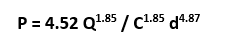
In the event of a fire in a building, once the sprinkler system has detected the fire, the water must be discharged at the required flow rate and spray pattern over the area of protection. The amount of water discharged from a sprinkler can be expressed using the following formula:
Q = K√P
Where;
Q is the water discharged in litre/minute.
K is a constant for the sprinkler.
P is the pressure at the sprinkler in bar.
The shape of the sprinkler deflector determines the spray pattern, water droplet size and area of coverage. There are a wide range of sprinklers designed for different purposes. It is therefore essential that the correct sprinkler is selected for the application under consideration.
As mentioned earlier, the function of a building determines the type of sprinkler system required including the spacing of the sprinkler heads required to ensure adequate coverage of the system in the event of fire conditions.
The spacing of sprinkler heads is largely dependent on the hazard type or hazard classification within the building. NFPA Standard 13 sets out spacing requirements which requires careful consideration when designing any sprinkler system.
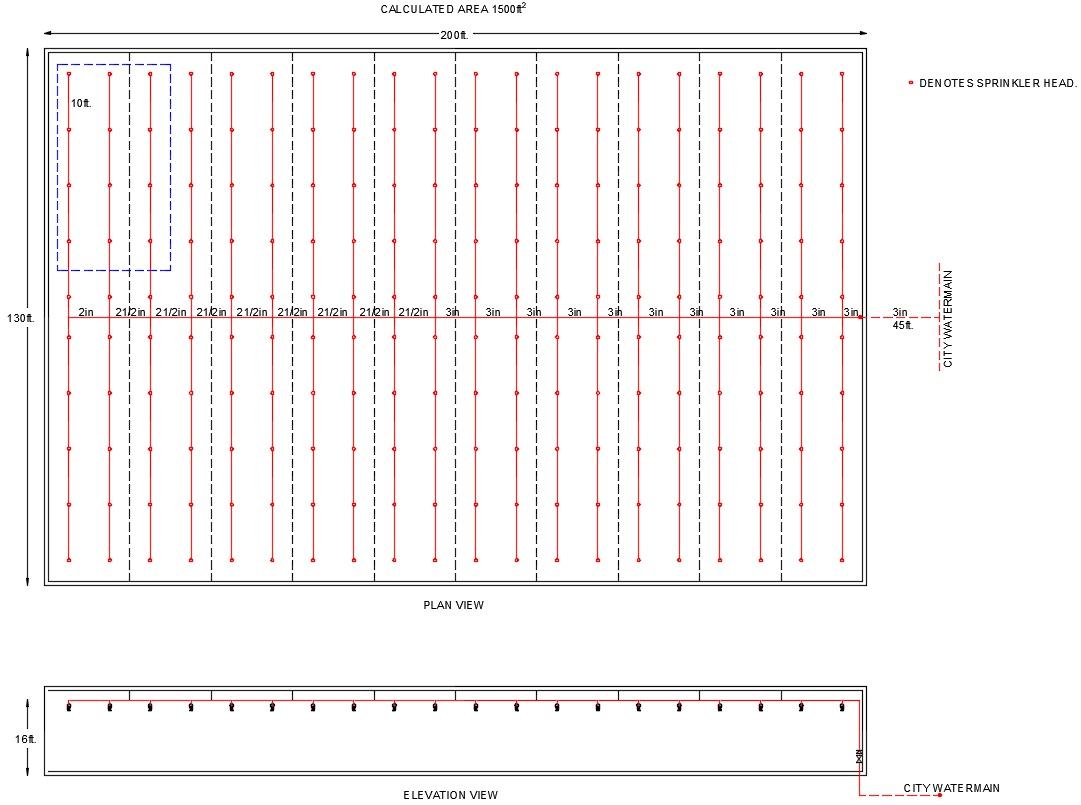
The NFPA standard provides an example case of a large warehouse facility measuring approximately 200 ft x 130 ft. The building has approximately 200 sprinkler heads and the example case focused on 12 remote sprinklers in operation (see sprinklers within the blue dashed line in Figure 1). The system operates with a design flow rate of 259.6 GPM.
An outline plan and elevation of the building is shown in Figure 1.
Figure 1: Building Plan & Elevation.
Based on this operating condition, the system pipe friction loss calculations have been performed using the Hazen-Williams formula, as follows;
Where;
P is the frictional resistance of the pipe (psi/ft).
Q is the flow in GPM.
C is the friction loss coefficient.
d is the internal diameter of the pipe in inches.
The Hazen-Williams Coefficient used in this worked example is C = 120 with the exception of the underground pipework which has a C = 150. The solution provided within the documentation utilises the equivalent pipe length method to estimate the loss associated with fittings in the system.
A key part of the completion of design calculations for any sprinkler system is the definition of the sprinkler coefficient, K value. This example utilizes a K factor of 5.6 for each sprinkler.
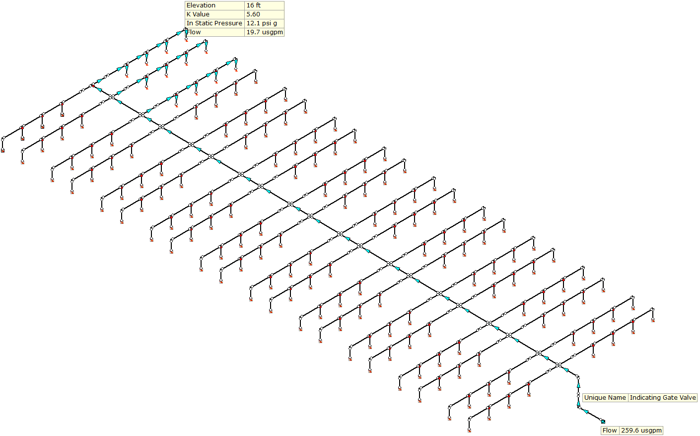
As outlined earlier, the example case focuses on 12 remote sprinklers in operation. The system was modeled in FluidFlow generating results which are a close match to those in the NFPA hand calculation. We can, however, expect differences between the two cases which can be attributed to the simplifying assumptions of using the equivalent pipe length method to determine the pressure loss across fittings. Note, FluidFlow doesn’t make this assumption and calculates the pressure loss according to the fitting characteristics. If for a specific design you have a requirement to use the equivalent pipe length approach, this method is also available in FluidFlow.
Figure 2: NFPA Sprinkler System Model.
The hand calculation notes a flow rate of 19.5 GPM serving the most remote nozzle whereas FluidFlow has determined a flow rate of 19.7 GPM. The static pressure calculated by the software is 12.1 psig which is an exact match of the hand calculation. The results for the branch pipes are noted as 40.2, 62.1 GPM in the hand calculation which again, compare well to the software result of GPM 40.2 & 61.3 respectively.
The minimum operating pressure for each sprinkler has been noted as 7 psi (0.5 bar). This minimum setpoint can be defined in FluidFlow and as such, any sprinklers which operate below this minimum pressure will be highlighted and clearly identifiable.
Sprinkler systems can be solved for any number or sequence of sprinklers activated at any given time. This solution can also be automated using the Scripting Module (Dynamic Analysis).
Using the pre-installed script option, it was established that this entire system has circa. 2421 ft of pipework with a total pipe volume of around 1.03m3.
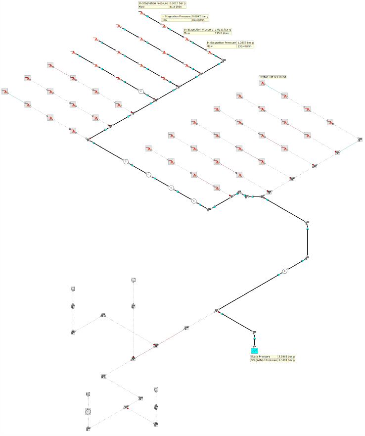
The next example case is for a yarn processing facility (Figure 3). The design system flow rate, in this case, is 1639.9 l/min. The design is based on STD steel piping with a Hazen Williams pipe coefficient of 120. Each sprinkler head has an associated K factor of 115.
Figure 3: Yarn Facility Sprinkler System Model.
This system was solved with just 15 remote sprinkler nozzles in operation. As can be seen in Figure 3, all other nozzles are turned off. The flow rate in the most remote nozzle is calculated as 81.5 l/min and the associated pressure at the system inlet based on the defined design flow rate is 5.5 barg.
References: