

When determining the friction loss in a pipeline transporting Newtonian fluids, we need to establish the value for Reynolds Number (Re) as this value is used to determine the pipe friction factor (f) which in turn is used when calculating the pipe friction loss.
The Reynolds Number (named after Osborne Reynolds) is a dimensionless number and can be described as the ratio of inertia forces to viscous forces within a fluid which is subjected to relative internal movement due to different fluid velocities. In the case where viscous forces dominate over interia forces, the flow is said to be laminar and the fluid flows in smooth straight orderly streamlines in the same direction whereas when inertia forces dominate, the flow tends to be unstable, and the flow pattern becomes irregular breaking up into random fluctuating eddies. The latter flow condition is said to be turbulent flow. Figure 1 and Figure 2 provide an illustration of the laminar and turbulent flow regimes respectively.
Laminar flow is therefore characterized by concentric layers traveling in parallel along the pipe length where the highest velocity is found in the pipe centreline and gradually decreases outwards towards the inner surface of the pipe.
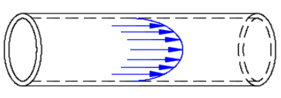 Figure 1: Laminar Flow.
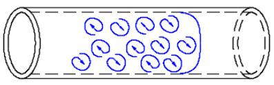
Figure 2: Turbulent Flow.
When developing the Reynolds concept for Newtonian fluids, it was discovered that it as possible to predict the velocity or flow rate at which the transition from laminar to turbulent would occur.
Interestingly, it was also noted that the velocity at which the flow regime changed back from turbulent to laminar was different. When flow was gradually increased, the change from laminar to turbulent occurred at a Reynolds Number of around 2500 and when the flow rate was gradually reduced it changed back from turbulent to laminar at a Reynolds Number of around 2000. Under “normal” conditions, a Reynolds Number of around 2100 was therefore taken as the critical Reynolds Number.
When analysing flow conditions in pipework, a Reynolds Number in the range of up to around 2100 is considered to be laminar and above 3100 is said to be turbulent. The range between 2100 and 3100 is referred to as the critical or transitional region. Estimating the friction factor in this critical region is complex as it may not be obvious if the flow is laminar or turbulent. The critical region is characterised by a combination of properties of the laminar and turbulent flow regimes.
When modelling piping systems in FluidFlow software, a warning message is enunciated to advise the user that the flow conditions are in this critical or unstable region. Users also can change the Reynolds Number setpoints of 2100 and 3100 if required.
The Reynolds Number is given by the equation: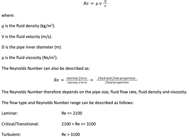
The Reynolds Number therefore depends on the pipe size, fluid flow rate, fluid density and viscosity.
The flow type and Reynolds Number range can be described as follows:
Laminar: Re <= 2100
Critical/Transitional: 2100 < Re <= 3100
Turbulent: Re > 3100
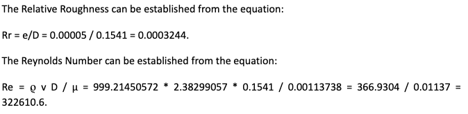
In determining the friction loss of a given pipe for a liquid flow system, the Reynolds Number together with the pipe Relative Roughness (Rr) can be used to determine the friction factor for the pipe using the Moody Chart. The Relative Roughness is the ratio of the absolute roughness of the pipe inner surface to the pipe inside diameter. The equation for the pipe Relative Roughness is:
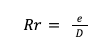
where:
e is the pipe absolute roughness (m).
D is the inside diameter of the pipe (m).
The Moody Chart
The Moody chart is a graphical representation of the friction factor (f) for all flow regimes (laminar, critical & turbulent) against the Reynolds Number at various values of the Relative Roughness of the pipe. Figure 3 gives an example illustration of the Moody Chart.
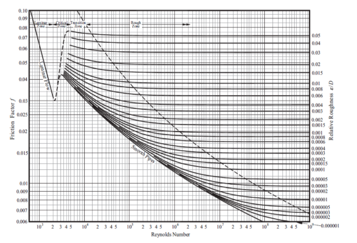
Figure 3: Moody Chart.
The following example as shown in Figure 4 demonstrates the calculation of Reynolds Number and Friction Factor for a pipeline transporting water at a flow rate of 160 m3/h. The Reynolds Number is calculated as 322610.6 and the Friction Factor is calculated to be 0.017027. This example is based on a pipe absolute roughness of 0.05 mm which is common for new or clean pipes. Users have the option to change the absolute roughness value to reflect your specific design conditions. 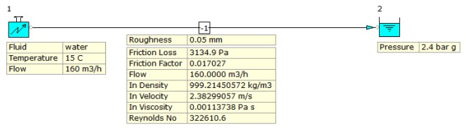
Figure 4: Calculation of Reynolds Number & Friction Factor.
The Reynolds Number in the hand calculation matches that of the software. If we check where the values of Reynolds Number and Relative Roughness intersect on the Moody Chart, we can then read-off the value for friction factor on the left of the chart. The value for friction factor is approximately 0.017 which correlates well with the software result.
We have already seen that a Reynolds Number in the range of up to around 2100 is considered to be laminar and above 3100 is said to be turbulent. Under laminar flow conditions, the pressure loss is proportional to the pipe length, flow rate, pipe diameter and fluid viscosity. When the flow is turbulent, the pressure losses behave proportional to the pipe length, square of the flow rate, pipe diameter and fluid viscosity.