

Geothermal power plants utilise hot water and steam from deep underground dry steam or hot water wells which is piped upwards and used to generate electricity. Technologies used in geothermal power plants typically includes dry steam, flash steam or binary cycle power plants.

Geothermal Power Plant in Kamchatka
Dry Steam Plant
In dry steam plants, hot geothermal steam is piped from geothermal reservoirs which then drives turbines. The turbine powers a generator which produces electricity and adds to the power distribution network. In dry steam plant, the steam is transferred from the well to the powerhouse via the gathering piping system. This piping system generally consists of one or more large diameter mains pipelines which collects the steam from the smaller diameter pipelines connected to each wellhead. As the main pipe approaches the powerhouse, the mass flow rate increases as each wellhead is connected into this common mains pipeline. One of the main considerations in the design of the gathering system is the selected diameter of the pipelines. For steam transportation pipelines, an allowable maximum velocity of circa 50 to 60 m/s for large diameter lines (>300mm pipes) whereas for smaller diameter pipes the velocity of circa 20 to 25 m/s is recommended. These velocity limits are recommended as the presence of water droplets or fine solid particles carried by high velocity steam can cause erosion of valve seats, bends as well as any other exposed parts.

Larderello geothermal power plant in Tuscany, Italy
At the well, there is a valve arrangement with steam purifier (inline axial centrifugal separator) which is designed to remove water droplets and particulate matter from the steam before it enters the piping system. The steam pipelines are fully thermally insulated and typically include expansion loops to accommodate any pipe movement. Steam traps are positioned strategically along the pipeline to remove condensate which is then transferred by a separate piping system to holding ponds before being reinjected. As the main gathering line approaches the powerhouse, a safety relief valve station is provided to permit the safe removal of steam in the event of turbine trip. Safety pressure relief valves can be automatically sized in FluidFlow to ISO & API Standards. Experience shows that it is better to operate the wells in a steady open state instead of changing between open and closed positions.
Flash Steam Plant
Single-flash steam plant is said to be the most widespread type of geothermal power plant. This plant is often the first power plant type installed at a newly developed liquid-dominant geothermal field. In geothermal wells which produce a two-phase mixture of liquid and steam, the single-flash plant offers a simple method of converting the geothermal energy into electricity. The mixture is firstly separated into two distinct liquid and steam phases with a minimum loss of pressure. This step is completed in cylindrical cyclone separators where the water and steam phases separate due to their inherent density differences. Separators are often positioned at the powerhouse, at satellite stations in the geothermal field or at the wellhead.

Geothermal power station near to the active volcano Apo. Mindanao, Philippines
One of the main considerations in the design of the gathering system is the pressure loss in the steam lines from the wellhead to the powerhouse. The pressure loss in steam pipelines is a function of the configuration of the piping system such as pipe length, diameter as well as the mass flow rate and physical properties of the steam. The most critical design parameter is the pipe diameter since the pressure drop is the function of internal diameter to the fifth power. Installing larger diameter pipes reduces the pressure loss however the extra cost of installing larger diameter pipelines may not be feasible. An optimum pipe diameter should be selected based on a thermodynamic study whilst also giving due consideration to capital cost. Software tools can assist with selecting optimum pipe diameters and FluidFlow offers three automatic pipe sizing approaches; Economic Velocity Sizing, Design Velocity Sizing and finally, Design Pressure Gradient Sizing.
The pressure loss in liquid pipelines is less of a concern since the liquid shall be disposed of by injection. However, high pressure losses may require pumps to maintain sufficient reinjection pressure.
The pressure loss in two-phase (steam-liquid) pipes is a much more complex phenomenon and difficult to predict accurately using tools such as spreadsheets as this approach doesn’t accurately consider the interaction of connected equipment. The solution of two-phase pipe flow systems is further complicated by the presence of different flow patterns which can change with pipe orientations etc. The mechanism for pressure loss is different for each flow pattern and therefore the use of a suitable software tool can assist greatly in this regard. FluidFlow includes several two-phase correlations and determines the flow pattern in each pipeline and solves accordingly. The software also plots the flow pattern map for each pipe segment. This allows the designer to identify the flowing conditions, flow regime and also identify how close the pipeline is to undesirable flow regimes such as slug flow conditions.
The double-flash steam plant is an evolution of the single-flash plant in that it typically can produce around 15 to 25 % additional power output for the same geothermal fluid conditions. The main difference is the presence of a second flash process which takes place on the separated liquid leaving the separator. This process generates additional steam at a lower pressure than that of the primary steam. This system therefore extracts even more energy by comparison to a single-flash system.

Krafla Geothermal Power Station in Iceland
In double-flash steam plant, several different piping arrangements (in comparison to single-flash plant) can be utilised to provide the additional flash process. They can generally be summarized as follows:
- Two-phase pipe connections from each well to satellite separation stations in the field. High and low-pressure steam lines are then derived from each satellite separation station and piped to the powerhouse. Hot water pipelines from the satellite stations is then reinjected to the wells.
- Two-phase pipe connections from each well to satellite separation stations in the field. High pressure steam lines and hot water lines derived from each satellite separation station and piped to the powerhouse. The power house includes separators where short low-pressure steam pipelines are connected to the turbines and hot water pipelines from the powerhouse are piped to the injection wells.
- Separators at each well head with high and low-pressure steam lines piped to the powerhouse. Hot water is piped from each production well to the injection wells.
- Two-phase pipe connections from each well piped to the powerhouse with separators located at the powerhouse. This system features short lengths of high and low-pressure steam lines to the turbines. The hot water pipelines are piped from the powerhouse to the injection wells.
A combination of the above arrangements may also be considered depending on the field conditions. The final selected design solution will take account of geofluid conditions, field conditions, well positions, topography position of powerhouse etc.
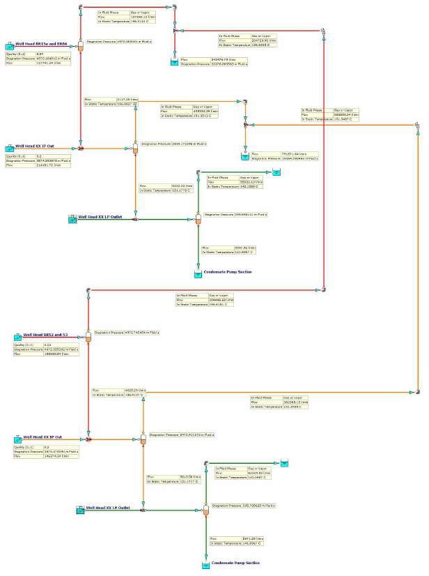
Figure 1 provides an illustration of a double-flash two-phase flow system as modeled in FluidFlow.
Flash steam plants are very common and use fluid temperatures in the range of circa. 182oC.
Binary Cycle Plant
Binary cycle power plants use the warm geothermal fluid (typically below 204oC) to heat a secondary fluid (such as isobutane) which exhibits a much lower boiling point. The fluids are kept separate with heat energy transferred from the geothermal fluid to the secondary fluid via a heat exchanger. This causes the secondary fluid to flash into steam which drives the generator turbines.
Binary cycle power plants are essentially closed-loop systems and virtually only water vapor is emitted to the atmosphere. The most common geothermal resources exhibit temperature below 149oC and as such, a considerable proportion of future geothermal electricity could come from binary cycle power plants.
A combination of both flash steam and binary cycle technologies has also been utilized effectively to take advantage of both technologies. In this plant, the flashed steam is first converted to electricity with a backpressure steam turbine and the low-pressure steam exiting the turbine is then condensed in a binary system. This allows for the effective use of air cooling towers with flash applications and takes advantage of the binary process. The flash/binary system has a higher efficiency where the well field produces high pressure steam while the elimination of vacuum pumping of non-condensable gases allows for 100 percent injection. Examples of these systems include the Puna Geo Venture facility in Hawaii where the geothermal fluid is over 316oC, the Upper Mahiao geothermal facility in the Philippines as well as several power projects in New Zealand.
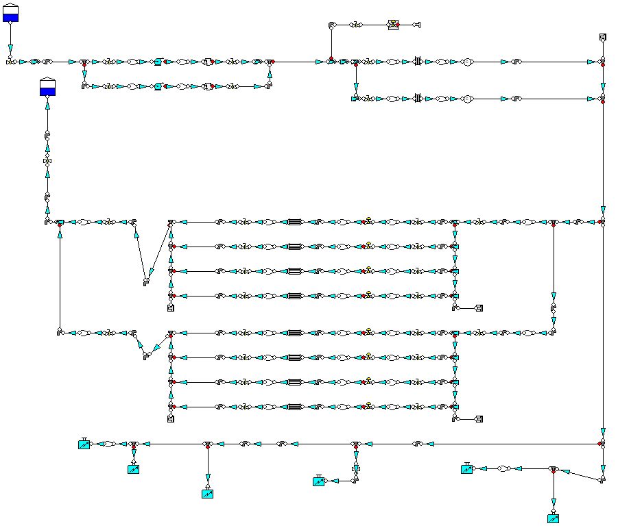
A cooling system is essential for the operation of modern geothermal power plants. Cooling towers prevent turbines from overheating and prolong facility lifespan. Many geothermal power plants use water cooling systems. Figure 2 provides an illustration of a cooling water system as modeled in FluidFlow.
FluidFlow software is used to design and model geothermal two-phase flow systems with separator stations, injection systems as well as cooling water systems. Companies which use FluidFlow to model geothermal piping systems include Philippine Geothermal Production Company, MTL Consulting Engineers in New Zealand and EFLA Consulting Engineers in Iceland.
FluidFlow is used by EPC’s as well as owner operators to design, develop and optimise piping systems for geothermal, coal and natural gas power plants. The systems modeled include natural gas delivery systems, water and steam systems (single and two-phase), air systems, ash handling systems, chemical systems and water treatment systems. As part of this process, designers utilise the powerful automatic equipment sizing tool to size pipes, fans, pumps, control valves, safety relief valves and orifice plates.
This discussion attempts to outline some of the basic principles of geothermal power plant systems. Further reading is recommended and the references outlined serve as a useful resource.
References:
- Pressure Drop in Large Diameter Geothermal Two-Phase Pipelines.
- A Guide to Geothermal Energy and the Environment, Geothermal Energy Association.
- Flow and Heat Transfer in Geothermal Systems, Aniko Toth, Elemer Bobok.
- Geothermal Power Plants Principles, Applications, Case Studies and Environmental Impact, Ronald DiPippo.
Explore FluidFlow's Two-Phase module here.