
Pipework: One of the most important tasks in plant design is the sizing of the process pipework.
Sizing your pipework incorrectly will have a major impact on plant capital cost, operating costs and plant reliability.
Piping always represents a significant part of the total installed cost on any plant, typically 10–20% in process plant and up to 80% of the capital cost in long pipeline transport projects. Plant maintenance and energy usage associated with fluid transport add to these costs. As a designer, it is your responsibility, to make the most effective design possible.
With this in mind, we ideally need a way of comparing the economic performance of piping in order to make informed decisions. Pipe sizing decisions should be made by comparing capital and operating costs, which necessitates access to up to date cost data, pipe run lengths and plant design requirements such as flows, temperatures and pressures. Paradoxically in many design projects it is often uneconomic to carry out an economic design of each pipe unless you use the assistance of a suitable software package.
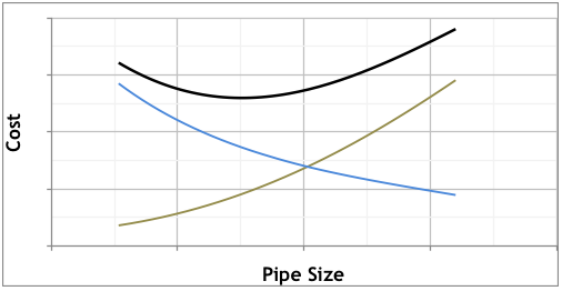
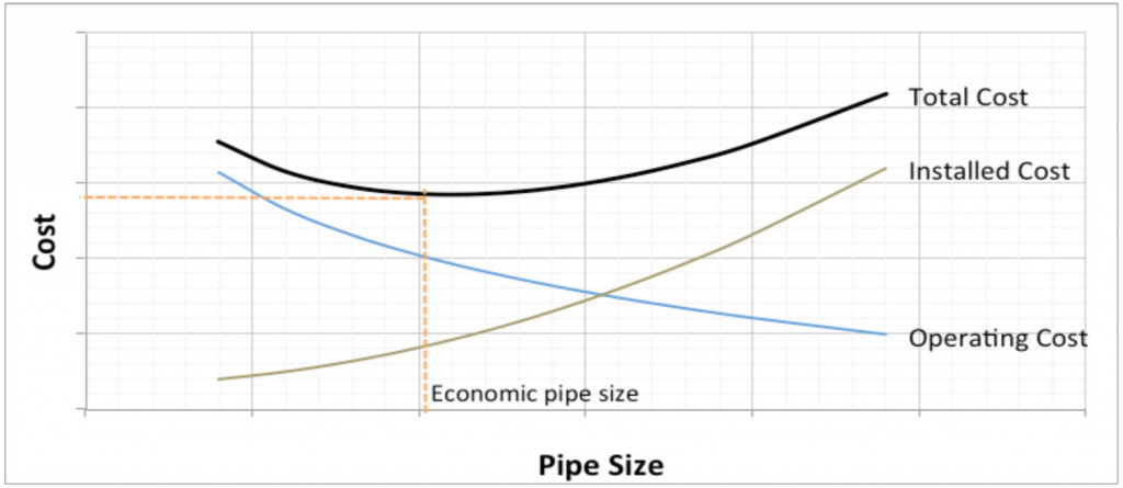
The chart below shows such an approach. Installed costs include material, installation
There are many computer software applications that help size pipes however, you need to examine the basis for such programs otherwise significant errors will nullify the validity of the program for this purpose. For example, the fluid phase-state and flow characteristics are most important considerations and as such, would you use the same criteria to size a pipe transporting cold water as a pipe transporting steam condensate?
The most beneficial approach is to size the pipework together with other fluid equipment items such as pumps, control valves, heat exchangers etc and in doing so, achieve a total system design. This is feasible only by using specialised software.
As we have stated, the most complete method for pipe sizing is based on economic velocity but it is worth noting that this approach should be used with caution. There are clearly many situations where pipe sizing to economic criteria should not be used. Some examples are; pump suction pipework, fluids containing solids that may settle, two-phase flow, non-Newtonian liquids, steam condensate lines and pipes that are operated intermittently, an example of such plant would be a fire protection system.
We should also remember that it is not necessary for pipe sizing to be exact. This is because we will usually select a pipe size based on standard pipe sizes. Since the application of pipe sizing rules can never be exact, engineers often use simpler approaches such as sizing to a given pipe velocity or a specific pressure gradient. Fluid flow literature contains numerous references to pipe sizing velocities and/or pressure gradients. Some of the disadvantages of using the simpler methods are that recommended velocities vary with each fluid and each piping material, making the process of always using the appropriate recommended velocity error-prone.
Another disadvantage is that recommended velocities change with time. As an illustration, in the 1980’s the most economic velocity for pumping water through steel pipes was around 2 m/s, 30 years later the economic velocity for pumping water is around 1.3 m/s. This reflects the relative large increase in energy costs compared to capital costs over this time period.
Nevertheless, it is important to select the “best” standard pipe size, so let’s follow the logical steps required to achieve this goal for a Newtonian fluid below its boiling point.
Literature References:
1. Updating the rules for pipe sizing – Durand et al – Chemical Engineering Jan 2010
p48.
2. Rules of Thumb for Chemical Engineers 4th Ed – Branan, p7-9.
3. Piping Calculations Manual – Menon.