

Pumps in Parallel
Pumps are often installed in Parallel in systems which exhibit considerable variations in flow or when the system has variable flow requirements and when these requirements can be achieved by switching the parallel pumps on and off. Typically, pumps installed in parallel are of a similar type and size. The pumps however can be of a different size or the pumps can be speed-controlled which of course means the pump performance curves will be different.
Figure 1 provides an illustration of a system with two identical pumps installed in parallel. The image shows how non-return valves are installed in series and downstream of each pump. This is to prevent bypass circulation when a pump is not running.
The total system performance curve for parallel pumps can be determined by adding Q1 and Q2 for every value of head which is the same for both pumps, i.e. H1 = H2. As the pumps, in this case, are identical, the resultant composite pump curve has the same maximum head value, Hmax but the maximum flow Qmax is twice as large. So, for each value of the head, the flow is double that of a single pump in operation.
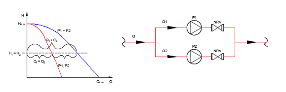
Fig 1: Pumps in Parallel.
Pumps are sometimes installed in parallel in pressure booster systems for water supply and for water supply in large buildings. Operational advantages can be achieved by connecting two or more pumps in parallel instead of installing just one single large pump. The total pump output is usually only required for a limited period. If a single pump was used in this instance, it would operate at a comparatively lower efficiency.
When a number of smaller pumps are installed in parallel, the system can be controlled to optimise or minimize the number of pumps operating and the pumps which are on will operate at or close-to the BEP (best efficiency point). To operate at the most optimal point, one of the pumps installed in parallel must have variable speed control.
The composite pump chart for pumps installed in parallel can be plotted in FluidFlow as shown in Figure 2. 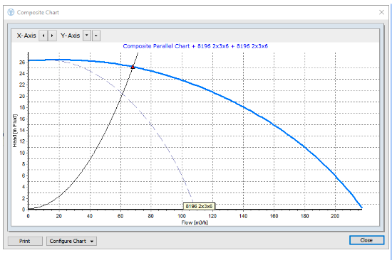
Fig 2: FluidFlow Composite Pump Chart - Pumps in Parallel.
Pumps in Series
Many pumping applications require fluids to be transported over long distances and against high static heads or total heads which are well in excess of the head that can be developed by a single pump. Examples of such scenarios would be, pumping tailings, power station ash, underground fill and pumping concentrates. Centrifugal pumps are occasionally installed in series to increase the operating range and standby capacity of the plant. Multi-stage pumps can be considered as a series type installation of single-stage pumps. However, single stages in multi-stage pumps cannot be decoupled.
If one of the pumps in a series type installation is not operational, it causes considerable resistance to the system. In an effort to overcome this, a bypass with non-return valve could be installed as shown in Figure 3.
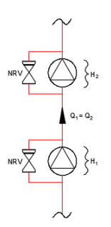
Fig 3: Pumps in Series.
The head associated with a given flow rate for pumps installed in series is can be determined by adding the single heads vertically as shown in Figure 4.
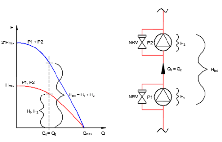
Fig 4: Pumps in Series.
The composite pump chart for pumps installed in series can be plotted in FluidFlow.
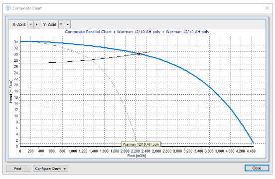
Fig 5: Composite Pump Chart - Pumps in Series.
Pump installed in parallel are typically identical pumps. There may however, be applications or scenarios where dissimilar pumps are installed. Figure 6 shows an example system which has a total of four pumps, three of which are operating.
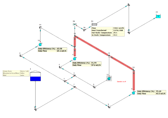
Fig 6: Composite Pump Chart – Dissimilar Pumps in Parallel.
Pump 10 and 11 are dissimilar pumps (two different sized pumps) installed in the system. The composite curve for any combination of pumps can be plotted in FluidFlow. Figure 7 shows the composite curve for pumps 10 and 11.
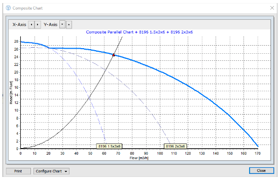
Fig 7: Composite Pump Chart – Dissimilar Pumps in Parallel.
References:
- Grundfos, The Centrifugal Pump.
- Grundfos, The Pump Handbook.