
Relief Valve Sizing – Pressure relief devices (PRD’s) are widely and effectively used to protect process equipment such as piping systems, pressure vessels, distillation columns and other equipment from pressures exceeding the design-pressure rating by more than a fixed predetermined amount. The aim of pressure relief valves is to prevent damage to equipment, prevent injury to personnel and to avoid potential risks to the environment.
PRD’s operate at a designated pressure, ejecting mass from the process which contains energy and the release of this energy reduces the process pressure. It is therefore critical that proper relief-valve sizing is carried out to ensure the fluid has sufficient flow area to exit the process thus safeguarding the safe operation of the process plant and equipment. It doesn’t end there however. As a safety pressure relief valve must be capable of operating at all times, in addition to proper sizing, it is also essential that due care has been given to the proper selection, manufacturing, assembly, testing, installation and maintenance of PRD’s. This is essential to ensure maximum protection in line with the design intent.
There are many different ways in which high pressure can be encountered in a system such as, failure of a control valve, external fire, thermal expansion of a liquid, or a reaction which becomes out of control. Each potential cause of overpressure is generally referred to as a scenario and all potential overpressure scenarios must be identified, characterised (as credible or non-credible) and documented prior to sizing a relief valve or relief system.
Pressure relief valves have been known to be sized and selected simply by matching the connection size of an available vessel nozzle or the size of the pipeline connection. Correct relief valve sizing is a complex process and there are many methods and tools available to size such devices. Two common Standards used for the sizing of pressure relief valves are ISO 4126 & American Petroleum Institute API RP520 Part I. The latter Standard is the most widely used for relief valve sizing. These standards outline several equations for sizing relief valves for various flow conditions such as liquid flow, gas flow (critical and sub-critical), steam flow and two-phase flow.
Before we consider the subject of relief valve sizing any further, we should firstly understand some of the terminology used.
Maximum Allowable Working Pressure (MAWP): This is the maximum gauge pressure permissible at the top of a completed vessel in its normal operating position at the designated coincident temperature specified for that pressure. The pressure is the least of the values for the internal or external pressure as determined by the vessel design rules for each element of the vessel using actual nominal thickness, exclusive of additional metal thickness allowed for corrosion and loadings other than pressure. The MAWP is the basis for the pressure setting of the pressure-relief devices that protect the vessel. The MAWP is normally greater than the design pressure but can be equal to the design pressure when the design rules are used only to calculate the minimum thickness for each element and calculations are not made to determine the value of the MAWP.
Set Pressure: This represents the pressure at which the device operates. Note, small amounts of leakage may occur at 92 to 95% of the set pressure for spring-operated relief valves.
Overpressure: This represents the pressure increase over the device set pressure, usually expressed as a percentage of the set pressure. Sufficient overpressure is required to achieve full lift.
Accumulation: This represents the pressure increase above the MAWP, usually expressed as a percentage of the MAWP. When the relief valve is at the MAWP, the overpressure and accumulation are equal.
Backpressure: This represents the pressure downstream of the relief device. This includes the superimposed backpressure and built-up backpressure due to fluid discharge from the relief device through the downstream piping.
It has already been noted that PRD’S protect equipment from pressures exceeding the design-pressure rating by more than a fixed predetermined amount. The ASME Boiler & Pressure Vessel Code Section VIII outlines design requirements for pressure vessels and the relief valves protecting them as a percentage of the maximum allowable working pressure (MAWP). Figure 1 provides an overview of the ASME recommendations.
The left-hand column outlines requirements for pressure vessels and the right-hand column outlines requirements for the relief valves. The entire figure is relative to the MAWP which is assigned an arbitrary value of 100%.
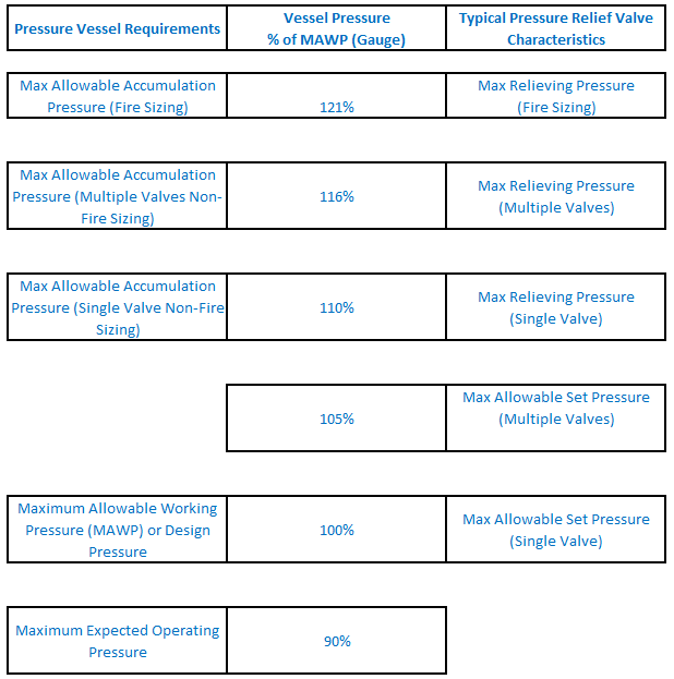
Figure 1: Pressure Relationships for PRVS.
Figure 1 shows that the vessel’s MAWP is equal to the relief valves maximum allowable set pressure. This relationship applies to vessels protected by a single device. If the vessel is protected by multiple devices, then one relief valve must be set no higher than the MAWP however the others can be set as high as 105% of the MAWP.
Relief valves are typically set to open at the MAWP. The anticipated operating pressure should be sufficiently low to prevent activation of the relief device during normal operation. The difference between the set pressure and the maximum operating pressure is known as the operating margin. The operating margin required depends on the type of relief device and the pressure control capability of the process.
Figure 1 also illustrates that, the allowable accumulation for pressure vessels protected by a single device is 110%. The exception to this case is fire exposure scenarios where the allowable accumulation is 121% of the MAWP. In scenarios where multiple relief devices are used for non-fire conditions, the allowable accumulation is 116%.
Relief valve sizing is a complex multi-step process. The following steps outline some of the considerations to be given as part of the sizing procedure.
- Define the Protected System: This can include several equipment items and can become quite complex for processes involving connected equipment with different pressure ratings. An example of such a scenario would be a relief device on the top of a distillation column. The device may protect the column, condenser, reboiler
and accumulator. - Position the Relief Devices: Establish where overpressure protection may be required. The following bullet points outline some locations where relief devices may be required:
- Pressure vessels require overpressure protection.
- Piping at risk of overpressure due to process control failure.
- Compressors, PD Pumps
and turbines require pressure safety relief devices on the discharge side for deadhead protection. - Relief devices should be fitted to liquid-filled lines where there is
risk of overpressure due to thermal expansion. -
Low pressure storage tanks require pressure and vacuum relief for normal operation. Tanks must also be protected from emergency events that could create abnormally high venting loads. - A vessel jacket requires its own overpressure protection.
3. Define the Overpressure Scenarios: There are typically multiple scenarios that may result in overpressure at each individual piece of process equipment. The plant P&ID’s should be reviewed in detail to identify these scenarios. Care should be taken at design-stage to ensure that you are working off the most up to date drawings. When all scenarios are identified, the next step is to
4. Choose the type of Relief Device: As the relief valve sizing calculations depend on the type of relief valve selected, we need to select an appropriate relief valve for the given application. The most common devices are spring-operated, balanced bellows, rupture discs, pilot-operated and rupture-pin relief devices. A combination of these devices may also be used. Reclosing relief devices should be considered from both a safety and reliability perspective.
5. Obtain Design Data for Relief Valve Sizing: The design data typically includes fluid physical properties such as density, viscosity, heat capacity,
6. Determine Flow Conditions (Single or Two-Phase): At this
Let’s consider a number of examples relief valve sizing cases.
Example Case 1: Hydrocarbon Mixture.
Figure 2 provides an illustration of a hydrocarbon mixture (butane & Pentane). This example is based on a hand calculation detailed in API RP520 Part 1. The design flow rate is given as 53,500 lb/h, the relieving temperature and set pressure
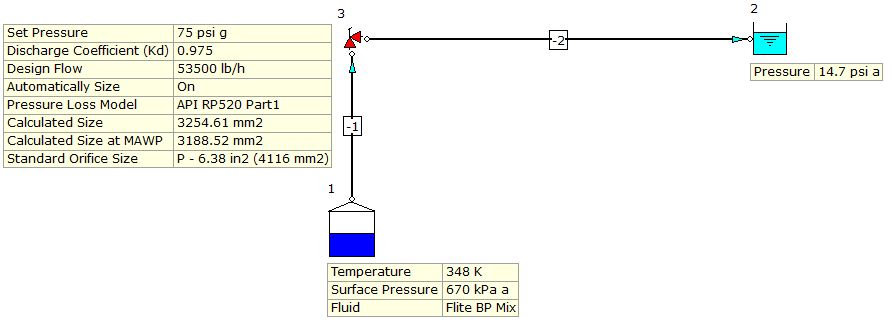
Figure 2: Relief Valve Sizing for Butane & Pentane Hydrocarbon Mixture.
The results developed by FluidFlow software reveal a calculated size at MAWP of 3188.5 mm2 which compares well with the hand calculation of 3179 mm2. The size is slightly different which is expected and this can be attributed to a number of factors:
- The physical properties (molecular weight etc) of our gas mixture is slightly different to that used in the hand calculation.
- FluidFlow does not assume gas ideality but solves for real gas conditions using an equation of state (three EOS to choose from).
- The hand calculation neglects the effect of connected piping whereas FluidFlow solves the system and considers the effects of any connected pipes.
Note that the result for Calculated Size is always greater than the Calculated Size at the MAWP (Maximum Allowable Working Pressure) due to pipeline and entry/exit losses. When using the API pressure loss model, FluidFlow suggests the closest matching standard size orifice available which can then be modeled in your system.
Example Case 2: Atmospheric Distillation Column.
The next sizing and selection case (Figure 3) is for an atmospheric distillation column of a crude oil refining process (Ref 5). The design flow rate of the gas is given in the publication as 50,000 kg/hr, molecular weight is 94 kg/kmol, the relieving temperature and pressure is 473 Kelvin and 4.725 barg respectively and the back pressure is given as 14.7 psi a (or 1 atm). The permitted accumulation is 16 % and the set pressure is 3.2 barg. The publication includes a hand calculation which notes that a discharge coefficient of 0.975 has been used and the calculated relief orifice size is given as 93.17 cm2.
It should be noted that the hand calculation includes simplifying assumptions of gas ideality and neglects any connected piping. The scenario was modeled in FluidFlow which solves for real gas conditions and includes the effects of any connected piping. The orifice size calculated based on API is 90.37 cm2 as outlined in Figure 3.
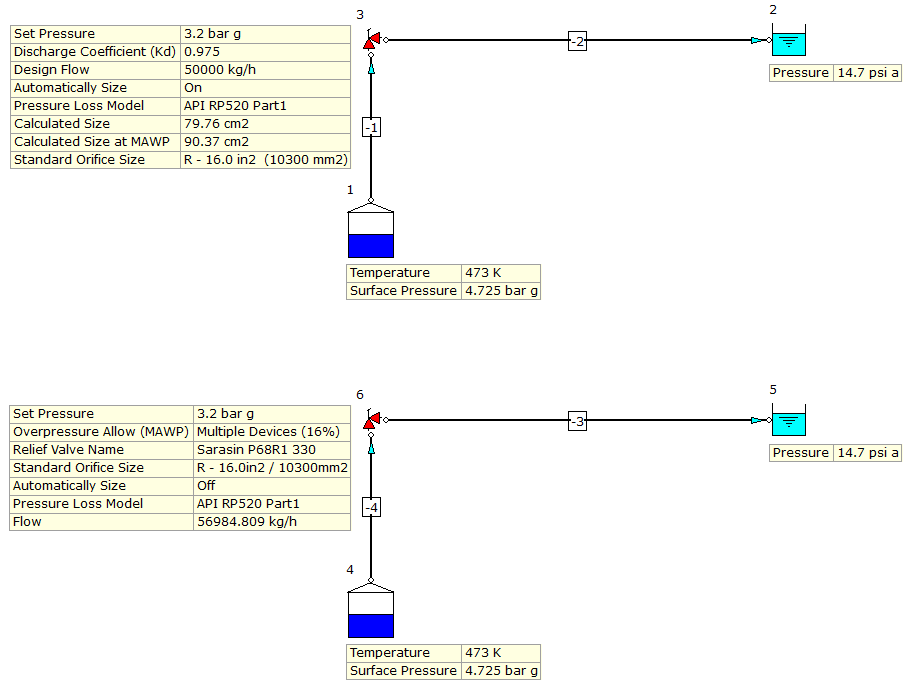
Figure 3: Relief Valve Sizing for Atmospheric Distillation Column of Crude Oil Refining Process.
The API Standard outlines Standard Orifice Sizes and as shown in Figure 3, FluidFlow has suggested the next closest size match is orifice size “R” (103 cm2). This matches the hand calculation. A Sarasin RSBD valve model for “R” orifice (size 103 cm2) was selected (refer to the bottom example in Figure 3).
The hand calculation applies a correction to establish the corrected flow rate based on orifice size “R” being used (103 / 93.17 * 50,000 = 55,275 kg/hr). An approximation to the FluidFlow results can also be established by a hand calculation as follows; 103 / 90.37 * 50,000 = 56,987 kg/hr. Figure 3 shows that when using orifice size “R”, the actual corrected flow rate established by FluidFlow is 56,984 kg/hr.
Example Case 3: Supercritical Butane.Supercritical fluids exhibit characteristics typical of both liquid and vapors and their physical properties can be strong functions of pressure and temperature and may deviate appreciably from ideal gas behaviour. The following is a sizing example for supercritical butane which for the purposes of this case, uses the API standard sizing equations. Note, this approach is based on air, the ideal gas law, an uninsulated vessel with no mass and no change in fluid temperature. CEP Magazine 2002 includes a hand calculation of this case and arrives at an orifice size of 0.034 in2. The design conditions are outlined in Figure 4. The relief valve set pressure is 800 psig with a 21% allowable overpressure for the fire case.
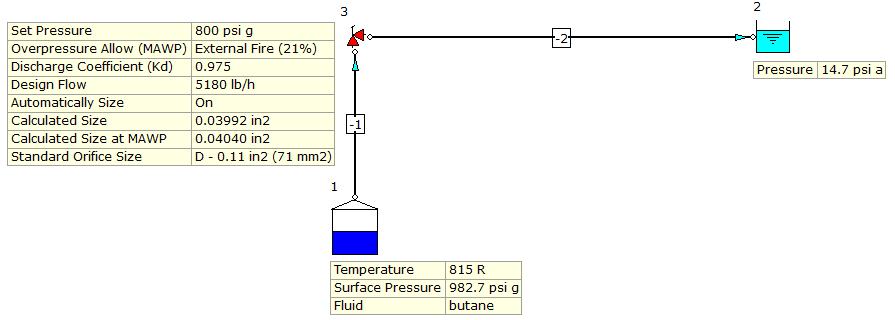
Figure 4: Relief Valve Sizing for Supercritical Butane.
FluidFlow has solved the case arriving at an orifice size of 0.040 in2 at MAWP which considering the software takes into account connected piping, real gas conditions etc, is a close match.
It is worth re-iterating that the sizing approach outlined in the API Standard for supercritical flow conditions is generally based on ideal gas and incompressible fluid behaviour and as such, may not be appropriate for specific cases. It may therefore lead to conservatively large orifice areas. FluidFlow software on the other hand doesn’t make these simplifying assumptions and solves for real gas conditions using an equation of state thereby offering a much more accurate solution.
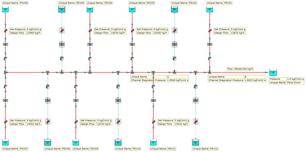
Example Case 4: Flare Relief Vent System.
The final example is of an extractive distillation plant which has 12 safety relief valves. There are two major relief scenarios: cooling water failure and external fire. The governing case in this instance is the cooling water failure as it occurs plant wide. External fire occurs only at localised areas and the relief loads come from just a small number of relief valves. This model therefore considers only the cooling water failure case. For simplicity, a set pressure of 5 kg/cm2 g has been assumed for all safety relief valves. This solution is based on an example case outlined in Chemical Engineering Magazine.
The relief rates are shown in Figure 5. The system is made up of a total of 395 M of pipework ranging in diameter from 4 to 12 inches.
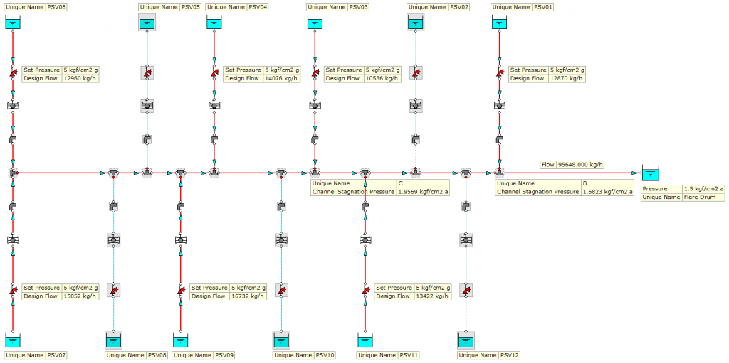
Figure 5: Flare Relief Vent System.
Based on the worked example in the hand calculation, the point B has a pressure of 1.6234 kg/cm2 a and point C a pressure of 1.9616 kg/cm2 a. This compares well with FluidFlow which has established a pressure of 1.62823 kg/cm2 a at point B a pressure of 1.9569 kg/cm2 at point C (see Figure 5). The total flow rate in this final line based on 7 of the 12 relief valves venting is 95,648 kg/hr.
Relief Systems Installation Tips:
- Safety relief valves should be connected to the vapor space of the protected equipment.
- To ensure reliable overpressure protection, it is best to install relief valves without any isolation valves. However, relief valves occasionally do no re-seat properly and start to leak. Therefore, in some cases, two safety relief valves are installed to allow replacement of relief valves that are leaking while the plant is in operation. This also facilitates regular testing and servicing of relief valves without interrupting plant operations. In scenarios where two relief valves are installed, isolation valves are provided for each relief device. This is to facilitate isolation of valve “A” for maintenance while bringing valve “B” online when required. In these cases, a ¾ inch bleeder valve with an isolation valve is recommended in between the isolation valve and the pressure relief valve. This is required because when valve “A” is isolated, the section between the isolation valve and the relief valve is still at the operating pressure of the column. The bleeder is therefore used to depressurise the system locally before the valve is taken offline.
- The inlet line should be self-draining back to the process vessel. This prevents accumulation of liquid that can corrode or block the system. Likewise, the outlet line from the pressure relief valve should be self-draining to the flare header. To meet this requirement, it is recommended the relief valves installed at high points in the system.
- When two relief valves are provided, it is mandatory to provide a mechanical interlock system between the respective isolation valves to ensure that one isolation valve is open at all times. This eliminates the potential risk of operator error, i.e. a scenario where both isolation valves are in the fully closed position rendering both relief valves unavailable to offer protection of the equipment.
- Whenever a bursting disk is installed upstream of a relief valve it is important to have a pressure indicator in the section between the two items. This is in case a pin hole leak occurs in the disk which would allow vapors to pass through to the section between the disk and the relief valve. Over time, the pressure up and downstream of the disk would reach equilibrium and the disk would never rupture.
- Relief valves in water, air or steam service are connected to the atmosphere through a short section of pipework. To keep this pipe free from liquid accumulation, a small weep hole is drilled at the lowest point of the pipe.
Economics
Economics also play a part in the design of safety relief systems. For instance, occasionally process industries use exotic materials, such as titanium and Hastelloy C. In such cases, instead of having a pressure relief valve made of Hastelloy C, it may be more cost effective to have a rupture disk made of Hastelloy C followed by a stainless-steel pressure relief valve.
In order to provide adequate protection of life and property, a safety pressure relief valve must be available and capable of operating at all times. It is therefore vital that the device has been carefully sized and selected. This article attempts to outline some of the main considerations when sizing and selecting safety relief valves. Further reading is recommended on the topic with the references outlined below serving as a useful starting point.
References:
- Sizing Calculations for Pressure-Relief Valves, Chemical Engineering Magazine.
- Sizing Pressure-Relief Devices, CEP Magazine.
- Rigorously Size Relief Valves for Supercritical Fluids, CEP Magazine.
- American Petroleum Institute, API RP520 Part 1.
- Sizing & Selection of Pressure Relief Safety Valves, Eastern Refinery Ltd.
- ASME Boiler & Pressure Vessel Code Section VIII.
To explore this subject further, please see a webinar recording below giving an overview of how FluidFlow can be used to automatically size your pressure relief devices to API & ISO standards: