
A centrifugal pump will operate by pumping as much fluid as it can and the amount of fluid transferred by the pump is a function of the resistance to flow, the amount of flow that can enter the pump and the physical capacity of the pump. As a centrifugal pump tends to not have any controls or sensors and as such, the pump will transfer fluid without regard for the required or design system flow or pressure requirement.
A classic example is a system which includes a filter. It was noted earlier that the flow rate produced by the pump is a function of system resistance. The system flow rate can vary considerably when the filter is new or clean compared to when the filter is dirty. The difference in pressure drops across the filter when clean vs dirty could be in the region of around 1.0 bar or higher. If transporting water at around 15 oC, this equates to around 10 m fluid. It may or may not seem significant or cause for any concern, however in a system that is designed to produce around 2.0 bar (20 m fluid), this pressure change is substantial.
Let’s consider an example scenario as shown in Figure 1. This system is required to provide a demand flow rate 100 m3/h. The system has been modelled and the pump has been sized. The pump exhibits a duty pressure rise of 10.0 m fluid (32.8 ft fluid) based on this design flow rate.-01-2.jpg?width=3960&name=Figure%201-1%20(1)-01-2.jpg)
Figure 1: Pump sized at 100m3/h.
The pump may now be selected based on the calculated operating conditions and fluid physical properties. The pump selected must therefore be capable of overcoming the pressure losses incurred within the system, in this case, 10.0 m fluid based on the filter being clean or new.
Figure 2 shows the system modelled with a manufacturer’s pump which has been selected based on the design operating conditions calculated in Figure 1. Once again, the filter is included on the basis it is clean and exhibits a pressure loss of 3.5 m fluid.
-01-1.jpg?width=3960&name=Figure%201-1%20(1)-01-1.jpg)
Figure 2: Vendor Pump Duty at 100m3/h with clean filter.
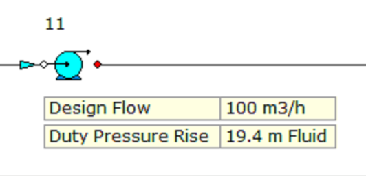
Let’s now consider a build-up of debris in the filter. Figure 3 once again shows the same system however, in this case, the filter is now dirty and exhibits a pressure loss of 12.9 m fluid (1.26 bar).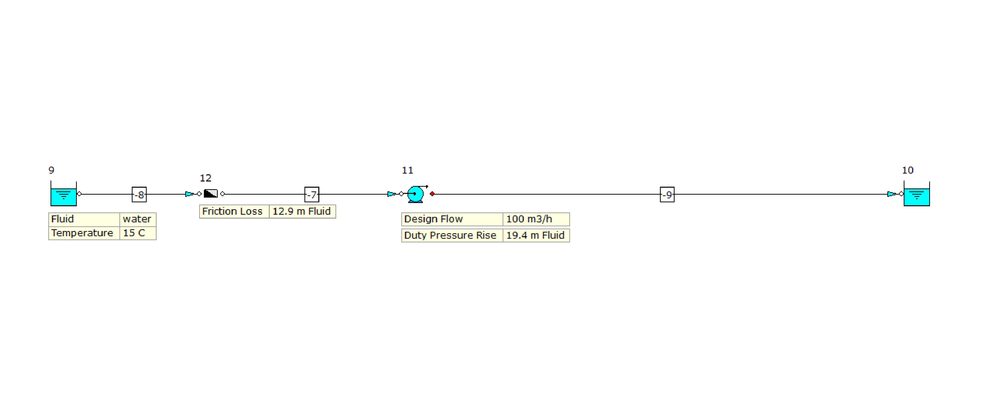
Figure 3: Pump Duty at 100m3/h with dirty filter.
As a designer, it would be necessary to size and select a pump capable of fulfilling the requirements of both operating conditions, i.e., 100 m3/h at 10.0 m fluid and 100 m3/h at 19.4 m fluid (63.6 ft fluid).
Another point worth noting here is, the pump net positive suction head required (NPSHr) will also need consideration as when the pressure losses increase as the filter gets dirty, the NPSHa will reduce. We therefore need to ensure we have sufficient NPSHa for the pump selected.
It may take some recalculation of the system losses for the various operating conditions in order to select a suitable pump for the application. In any case, the pump selected should operate within the range of 50 to 120% of the best efficiency point (BEP).
References:
- Pumps & Systems
.