
Two-phase gas-liquid flow is a common phenomenon in nuclear, geothermal, chemical, oil and gas and refrigeration industries where gas-liquid mixtures are transported in piping systems. Two-phase pipe flow is the simultaneous flow of a gas (or vapor) and a liquid exhibiting different physical properties through the same pipe. A typical example of two-phase flow is a water-steam mixture. The prediction of the fluid physical properties and pressure drop in two-phase pipe flow is of vast importance during the design and operation stages in all applications to ensure the fluid does not deviate from its operational envelope and cause damage to personnel, plant and equipment. Due to the complexities of two-phase flow, it is commonplace to apply modelling techniques to predict the behaviour and characteristics of two-phase flow.
The physical properties of the two-phase fluid are not constant or uniform throughout the piping system and flow-induced pressure drops can cause considerable changes in magnitude of one phase compared to the other. For instance, some of the liquid can evaporate (flash) due to pressure drop across pipelines or through an orifice which results in an increase in gas/vapor. FluidFlow assumes that instantaneous isenthalpic flashing occurs. The software also identifies the physical properties of the fluid at the inlet and outlet of each pipe and fittings. A common feature of two-phase flow systems is that the flowing velocities increase and the mixture density decreases.
In cryogenic applications, two-phase flows are usually a mixture of a cryogenic liquid along with its corresponding vapor. A mixture of liquid helium and helium vapor is a typical example. An advantage of two-phase flows is that it can provide isothermal heat sinks. Due to the latent heat of boiling, heat added to the liquid portion of a two-phase flow will contribute to the conversion of the liquid to vapor in the mixture but will not increase the mixture’s temperature. This characteristic is used in cooling schemes such as those found at the Hadron Collider, HERA and Tevatron magnets.
There are also a number of disadvantages to two-phase flows. In comparison to single-phase pipe flows, these flows typically have a higher pressure drop and flow instabilities may develop that result in pressure surges and vibrations. Incorrectly designed systems can also trap the vapor phase against surfaces resulting in inadequate cooling or energy transfer and many flow components such as pumps and flow meters may not function properly in two-phase flows. Furthermore, in cases where the flow is on an incline, the liquid may flow to the downhill side. This may therefore necessitate the use of shorter flow paths to maintain any desired liquid-vapor ratio.
Due to these issues and complexities, detailed modelling is required whenever two-phase flows are used in cryogenic systems, to ensure proper performance. Care must also be taken that a nominally single-phase (say pure liquid) flow in a system does not suddenly become two-phase due to heat inputs or pressure drops resulting in unexpected operating problems.
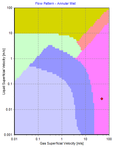
Two-phase mixtures flow in pipelines in several configurations or structures called flow patterns or flow regimes. This describes the arrangement and relative fractions of the liquid and vapor in the flow. In the case of horizontal or near-horizontal pipe flows, typical flow patterns are stratified smooth, stratified-wavy, elongated-bubble, slug, annular, wavy-annular and dispersed-bubble. Some of these flow patterns are shown in Figure 1. Typical flow patterns for upward vertical pipe flow are bubble, slug, churn, annular and dispersed-bubble.

The fluid flows in different flow patterns such as slug, churn and annular. Some of these flow patterns can generate dynamic fluid forces which in turn may induce structural vibration. Excessive vibration may lead to component failures which must be avoided as they can produce significant economic, environmental and even human losses.
Therefore, the knowledge of flow conditions including flow pattern as well as flow-induced vibration (FIV) can have a significant impact on the proper design and operation of piping systems.