

In two-phase liquid-gas flow, the distribution of the respective liquid and gas phases in the pipeline is an important aspect of their description. Their description descriptions exhibit some commonly observed flow structures known as two-phase flow patterns or flow regime. These flow patterns have particular identifying characteristics. Pressure drops and heat transfer coefficients are closely related to the local two-phase flow structure of the fluid. As a result, the prediction of two-phase flow pattern or structure is an important aspect of modelling two-phase pipe flow.
Some of the flow patterns often encountered in horizontal pipe flow are stratified flow, stratified-wavy flow, bubble flow, plug flow and slug flow, annular flow and mist flow. The following offers an outline description of some flow patterns in horizontal pipelines:
Bubble Flow: The bubble flow regime is characterized by the gas bubbles which are dispersed in the liquid phase often with a high concentration of bubbles in the upper half of the pipe due to their buoyancy. In the case where shear forces are dominant, the gas bubble tend to be distributed more uniformly in the pipe. In horizontal flow, this flow regime typically only occurs at high mass flow rates.
Stratified Flow: In horizontal flow, this flow regime typically occurs at low liquid and gas velocities and complete separation of the phases occurs in the pipe. The gas-phase travels at the top of the pipe and the liquid at the bottom and the phases are separated by an undisturbed horizontal interface.
Stratified-Wavy Flow: If the velocity of the gas phase in a stratified condition is increased, waves form on the interface and travel in the same direction as the direction of flow. The amplitude of these waves is dependent on the relative velocity of the two phases. The crests of these waves tend not to reach the top of the pipe.
Plug Flow: As the gas velocity is increased further, the interfacial waves become larger and can wash to the top of the pipe. The plug flow condition can then occur and exhibits liquid plugs that are separated by elongated gas bubbles. The elongated gas bubbles are smaller than the pipe such that the liquid phase is continuous along the bottom of the pipe below these elongated bubbles.
Slug Flow: At higher gas velocities, the diameter of the elongated gas bubbles become similar in size to the height of the pipe. The liquid slugs separating the elongated bubbles can also be described as large amplitude waves.
Annular Flow: As the gas flow rate is increased even further, the liquid forms a continuous annular film around the perimeter of the pipe. This film tends to be thicker at the bottom than at the top due to gravitational forces. The interface between the vapor core and liquid annulus is disturbed by small amplitude waves and droplets can be dispersed in the vapor core.
Mist Flow: At very high gas velocities all the liquid becomes stripped from the inner surface of the pipe and entrained as small droplets in the vapor phase.
Some of the flow patterns often encountered in vertical pipe flow are bubble flow, dispersed bubble flow, slug flow, churn flow, annular flow, and mist flow. The following offers an outline description of some flow patterns in vertical pipelines:
Bubble Flow: Discrete gas bubbles are dispersed in the continuous liquid phase. These bubbles can vary considerably in size and shape however they are typically almost spherical and are much smaller than the pipe diameter.
Slug Flow: Increasing the gas void fraction results in the bubbles become very close such that the bubbles collide and combine to form larger bubbles which tend to be similar in dimension to the pipe diameter. These larger bubbles are separated from one another by slugs of liquid.
Churn Flow: Increasing the velocity of flow results in the structure of flow becoming unstable with the fluid traveling up and down in oscillations but with net flow in an upward direction. This flow regime is an intermediate regime between slug and annular flow. In smaller diameter pipes, churn flow may not develop at all and the flow structure may pass directly from slug to annular flow. Churn flow is a regime which typically should be avoided in two-phase transfer pipelines such as refrigerant piping networks or from a reboiler back to a distillation column because the mass of the slugs may have destructive consequences for the piping system.
Annular Flow: When the interfacial shear of the high-velocity gas on the liquid film becomes dominant over gravity, the liquid is expelled from the centre of the pipe and flows as a thin film on the wall while the gas flows as a continuous phase through the centre of the pipe. The liquid may be entrained in the gas phase as small droplets to the extent that the fraction of entrained liquid may become similar to that in the film. This flow regime is particularly stable and tends to be the desired flow pattern for two-phase liquid-gas pipe flow.
Wispy Annular Flow: As the flow rate is increased further, the entrained droplets may form transient coherent structures as wisps or clouds of liquid in the central vapor core.
Mist Flow: At high gas flow rates, the annular film becomes thinned by the shear of the gas core on the interface until it becomes unstable and is destroyed such that all the liquid becomes entrained as droplets in the gas phase.
The flow pattern in a given two-phase pipe is a strong function of the parameters listed below:
Pipe diameter.
Angle of pipe inclination.
Liquid and gas flow rates.
Liquid and gas physical properties including densities, viscosities and surface tension.
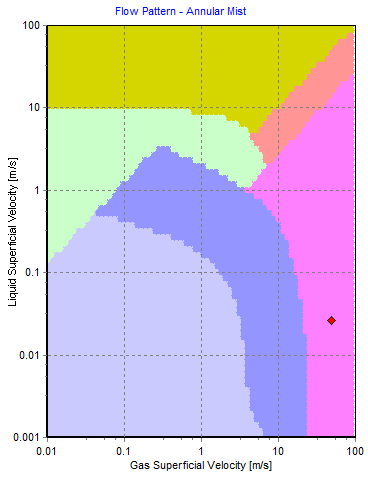
FluidFlow generates a flow pattern map for each pipe in the two-phase liquid-gas flow system. Figure 1 below shows the duty point for a sample pipe which indicates the flow regime is annular mist as noted at the top of the image. This helps the designer identify the flow characteristics in each pipe.
References:
- Fluid Flow Handbook, Mc Graw Hill.
- Wolverine III.