
The design of two-phase liquid-gas pipe flow systems is a complex process. It can be common practice for engineers to use template design calculation sheets for two-phase systems. These calculation sheets often utilize rules-of-thumb as part of the template for design. This can result in the failure to acknowledge inherent differences from one project to the next. In large-scale projects such as geothermal systems, errors in system design such as underestimating friction losses can become magnified resulting in poor design with inherent operational difficulties.
In this paper we will make a hand calculation for a pipe system that has both vertical and horizontal pipe runs and then compare the results to those that can be obtained from a software based solution.
This piping system has 358ft of level pipe, three vertical rises of 10ft each and one vertical rise of 50ft. We wish to evaluate the type of flow and expected pressure drop.
Table 1: Fluid Physical Property Data.
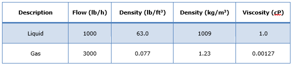
Pipe Data: 3 Inch, Schedule 40 Stainless Steel (I.D. 3.068 in). Pipe Relative Roughness: 0.000587.
A hand calculation has been completed for this system, details of which are outlined below.
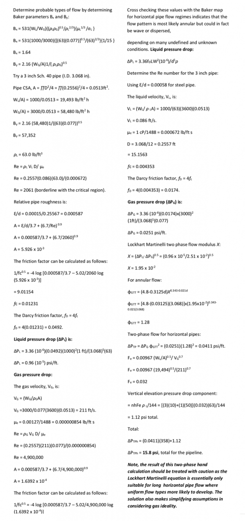
This calculation is based on the gas having a viscosity of 0.00127 cP and a density of 1.23 kg/m3.
To make a comparison, a model has been created in FluidFlow software. For convenience, based on the fluid physical properties, the liquid and gas used in the model is water and air. It is worth noting that the viscosity of air and water in FluidFlow is 0.018 and 1.13 cP respectively. This represents a very slight difference to the hand calculation.
FluidFlow Solution
The first step is to build the model using the above data. The model should appear as per Figure 1 below. Note, two Known Flow inlet boundaries have been defined, one with air and one with water. The connecting pipe has been set to 0.5m in length, 3 inch in diameter and the statues of these pipes (nods -1 & -3) have been set to “Ignore Pressure Loss” as, these pipes are only provided for model connectivity purposes and do not form part of the overall calculated system.
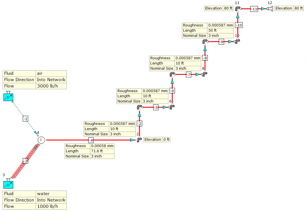
Figure 1: System Model.
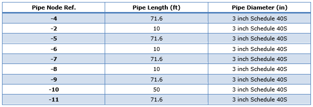
The system consists of a total length of 358ft of level pipe. As we have a “stepped” system i.e., changes in elevation, we have simply split the 358ft into 5 equal level pipe segments of 71.6ft each. Details of the various pipe lengths are set out in Table 2.
Table 2: Pipe Data.
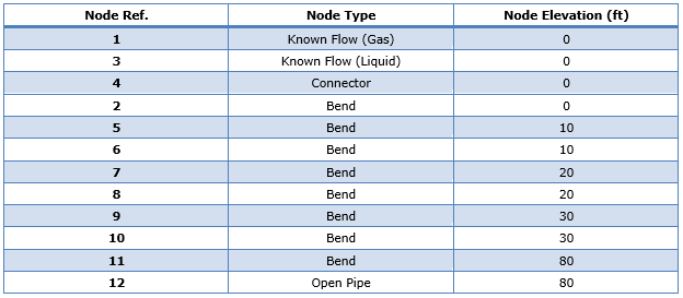
The node elevations have also been set in accordance with the system design criteria. Details of which can be seen in Table 3 below.
Table 3: Node Elevation Data.
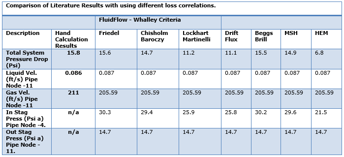
This system has been calculated using the various different two-phase pressure loss correlations available in FluidFlow. Table 4 provides details of the calculated results which are compared to the results provided in the literature.
Table 4: Table of Calculated Results.
Comparison of Results
- The first option selected is Whalley Criteria. This option lets the software select the appropriate method from the three correlations available when using this approach i.e., Friedel, Chisholm Baroczy & Lockhart Martinelli. In this example, FluidFlow has analysed the fluid physical properties (fluid viscosity ratio and mass flux) and has applied the Friedel correlation. Note, this correlation uses different equations for horizontal and vertical pipes. We can see that the results compare well with that in the hand calculation.
- Chisholm Baroczy: This approach dates back to the 1970’s and uses a two-phase multiplier. This is one of the more simplistic two-phase correlations. However, the results compare well when using this approach.
- Lockhart Martinelli: This forms the basis of the solution in the hand calculation. In general, it is accepted that this model should only be applied to horizontal pipe flow. This is also one of the more simplistic two-phase correlations and also dates back to the 1970’s. Again, the results compare well when using this approach.
- Drift Flux: This approach is recommended for modelling vertical or inclined pipelines.
- Beggs Brill: Recommended not to use this method for vertical upward flow as it under predicts pressure loss. It is difficult to assess the full effect of this in this particular example as only a fifth of this system consists of vertical pipework, i.e. most of the pressure loss occurs across the horizontal pipe segments.
- MSH: This approach is more useful when considering heat transfer and modelling single component fluids such as refrigerants. This method tends to lose accuracy when high vapor quality conditions are experienced in a system. This particular system has an outlet vapor quality of 0.75 (75%) and as such, it is considered that the results obtained using MSH may have a slightly lower level of accuracy when compared to, for example, the Friedel method.
- HEM: This method uses a simplified approach and averages the fluid density values. It also assumes the velocity, pressure and temperature between phases are equal. Due to the simplification of the modelling approach, it is recommended that this option should only be selected as a means of checking or validating results from the correlations noted above. It is also clear from the HEM approach that the total system pressure drop is significantly lower than that provided in the hand calculation and also when using other available loss correlations in FluidFlow.
Note, interestingly, the three approaches of Friedel, Beggs Brill and MSH which take into account flow orientation or flow regime offer a solution which is closest to the hand calculation example.
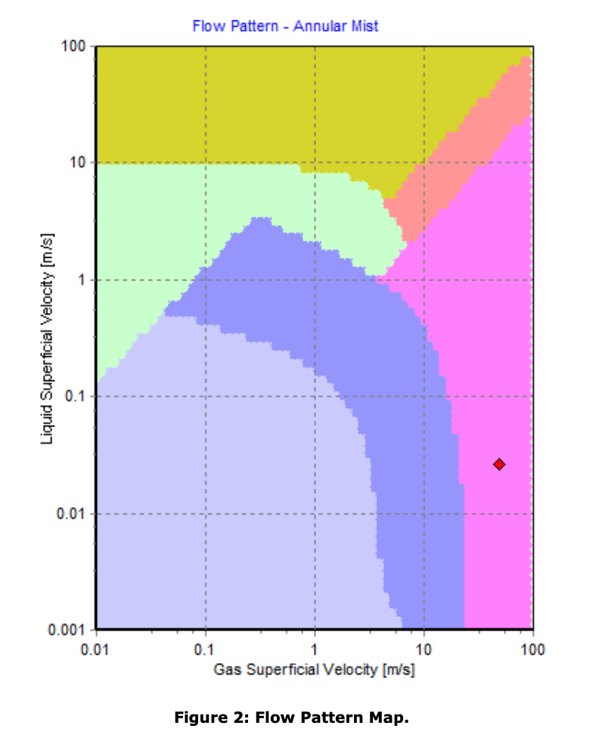
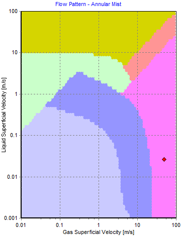
FluidFlow generates a flow pattern map for each pipe in the system. Figure 2 below shows the duty point for a sample pipe in this system which indicates the flow regime is annular mist which correlates well with the hand calculation.
Conclusion
The literature calculation is based on the gas having a viscosity of 0.00127 cP and assumes gas ideality. For simplicity, the model has been developed using air and water which has a viscosity of approx. 0.018 and 1.13 cP respectively (based on 15oC). This will therefore have a slight effect on the calculated results.
The “hand” calculation is based on ideal gas conditions. FluidFlow does not assume gas ideality but solves for real gas conditions using an equation of state and hence, provides more accurate result.
Based on the above, it is considered that the results provided by FluidFlow correlate well with the hand calculation and offers an accurate reflection of the system operating conditions. It is also considered that the Friedel correlation may be best suited for this particular application owing to the combination of both vertical and horizontal pipes.
Note, solving this system in a suitable software package allows the designer to consider different correlation approaches and also identify the flow pattern map for each pipe in the system.
The design of two-phase piping systems may pose a daunting task to the designer. However, having a useful and easy to use software tool can help eliminate the likelihood of data entry errors, enable better understanding of the operating performance the system, help identify unstable operating conditions and also, consider different design conditions without the need to refactor any hand calculations. Furthermore, once a design has been finalized, you can revisit in the future should the operating system require expansion or alterations.
Testimonial

“MAN Diesel & Turbo’s activities in the power plant sector are based on a well- established range of diesel engines and a rapidly growing gas engine offering. The products range from small emergency power generators to turnkey power plants with outputs of up to 400 MW. We use the liquid, gas, and two-phase modules of FluidFlow and make extensive use of its simulation capabilities for engineering subsystems as fuel gas lines or cooling water pressure systems, including for the development of new systems. Before we bought we carried out extensive product research and chose FluidFlow because of its completeness and value for money. We have had to make
occasional technical support calls and have been impressed by the responsiveness. We have found Flite Software to be extremely knowledgeable and helpful, really excellent.”
Norman Kurth, System Engineering, MAN Diesel & Turbo, Germany.