

The mass flow of fluid discharged through a safety pressure relief valve is typically a liquid or vapor however, it can be a combination of both liquid and vapor or in other words, two-phase flow. When considering pressure relief applications, it can be common for all or part of the liquid portion of the fluid to flash or change to its vapor phase-state as the pressure drops. The ratio of liquid to gas in the flowing fluid can be an important factor in determining the required relief valve orifice area.
Since two-phase flow generally has a decreased flow capacity compared to vapor-phase or subcooled (non-flashing) liquid flow, a greater relief orifice area is generally required for two-phase flow. Indeed, literature sources occasionally quote that the required relief area for two-phase flow is around two to ten times the area for single-phase flow. The larger area requirement results from the fact that when we have two-phase flow conditions, the liquid partially blocks the relieving area flow path of the vapor by which most of the energy is removed by evaporation from a vessel.
Oversizing of pressure relief valves can be as detrimental as undersizing. Oversizing a safety relief valve with two-phase flow can have dangerous consequences. Excessive fluid flashing can occur on the downstream side of an oversized relief valve which can cause the back-pressure build-up to the point that the relief device function becomes impaired. The result could potentially be a catastrophic vessel failure.
The selection of sizing method to be used for a two-phase flow application is a decision made by the designer. It is therefore vitally important that the designer has detailed knowledge of the process conditions. The use of an appropriate software tool can also help greatly with the relief valve orifice sizing task.
The design of two-phase safety relief valves can be a complex undertaking which is why an experienced expert should be consulted and a suitable software tool can help enormously with this challenge.
There are a number of published codes of practice and standards which discuss the topic of relief orifice sizing for two-phase flow conditions. These documents may help the designer choose the appropriate sizing methodology. Further reading of API 520 Part I and EN ISO 4126 will provide some useful information regarding suitable equations for a given design condition.
API 520 Standard Part I details an example hand calculation which considers a sizing case for propane with a volumetric flow rate of 100 gal/min and relief valve set pressure of 260 psig. The fluid temperature at the relief valve inlet is 60 F, the downstream back pressure is 10 psig and permitted accumulation is 10%. Based on the design conditions described in the document, the orifice area has been calculated at 0.208 in2. From this calculation, the standard orifice size “F” was selected (0.307 in2).
This example was recreated in FluidFlow software (Figure 1) and in doing so, a number of assumptions are required since the standalone hand calculation in API 520 doesn’t take into account the effect of connected pipes. Pipe sizes, lengths etc are therefore not described in the document. The model utilises an upstream and downstream pipe connected to the PRV and the design conditions are defined for the system.
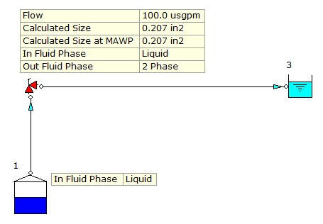
Figure 1: Relief Valve Sizing Model.
We have seen that the API Standard arrived at a calculated orifice size of 0.208 in2 whereas FluidFlow has calculated a size of 0.207 in2 (Figure 2). When using the API Pressure Loss Model in FluidFlow, the software automatically suggests the next closest standard size match which in this case, is orifice size F matching that of API 520 Part I.
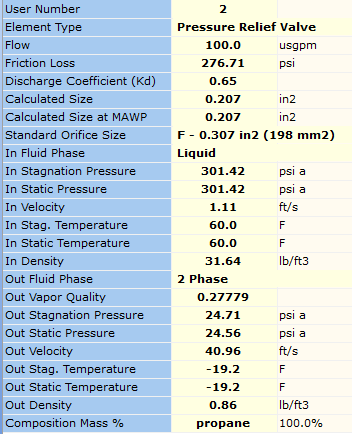
The example hand calculation makes reference to a density of 31.92 lb/ft3 for the propane at the inlet of the relief valve. Figure 2 notes that FluidFlow has calculated a density at this point of 31.64 lb/ft3.
The software has also detected flashing has occurred across the PRV and applied the appropriate pressure loss correlations. The fluid phase state is clearly visible at both the inlet and outlet of the relief valve.
In some cases, industry standard documents recommend that the relief valve manufacturer is contacted directly for advice for sizing relief valves for two-phase flow conditions.
Ensuring an emergency safety relief system design can either avoid or accommodate two-phase vapor-liquid flow is a particularly important aspect of the design process.