
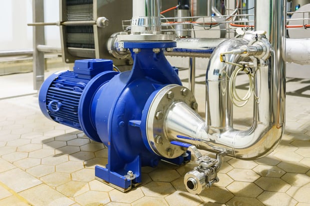
Centrifugal pumps are machines that move fluids from one place to another by raising the fluid pressure. When choosing a pump, the pump performance curve is an important tool to help select the right model and assess how well the system will perform.
Pump performance curves are often overlooked and undervalued in the realm of industrial pumps. Unfortunately, the individuals who would benefit most from these curves, such as mechanics and operators, typically do not have access to them. Meanwhile, those with control over the curves tend to store them away in a file or cabinet that is rarely accessed, and they do not share valuable information with the individuals who could use it most. This lack of sharing may be due to a lack of understanding of the information contained within the curves.
What is a Pump Curve?
A pump curve is a graphical representation of a pump's performance over a range of flow rates. It shows the relationship between the flow rate, head, efficiency, and power consumption of a pump. The curve provides a visual representation of the pump's ability to move fluid and the energy required to do so and is thus very useful in determining the most efficient operating point of a pump.
Understanding the Components of a Pump Curve
To understand the basics of pump curve operation, it is important to know the key components of a pump curve. These components include:
- Flow rate: This is the amount of fluid per unit of time moving through the pipeline, measured in gallons per minute (gpm) or cubic meters per hour (m3/h). The rated flow rate of a pump refers to its designed volumetric flow rate or capacity defined by either end-users or by pump manufacturers. This is dictated as the flow requirement for a system directly defined by end users or through detailed process design. Typically, this is padded with a 10% or 20% additional flow margin to cover for any uncertainties and future expansion requirements.
- Head: This is the amount of energy that the pump needs to transfer to the liquid in order to move it to its intended destination. It is measured in meters (m) or feet (ft) and represents the height to which the pump can raise the fluid. The pump head remains constant regardless of the fluid's characteristics, so the pump will be able to lift the liquid to the same height, regardless of its specific gravity.
- Power or Brake horsepower (BHp): the power required from the motor to drive the pump to deliver a given volumetric flow rate and head, measured in horsepower (hp) or kilowatts (kW). The easiest aspect of the pump performance curve to understand is the energy curve, also known as the brake horsepower (BHp) curve. This curve is typically a straight line, where the pump consumes a set amount of energy to maintain the shut-off head. As the flow increases, the horsepower consumption also increases. However, there are some duty pumps where the BHp may remain constant or even decrease at flow rates near the end of published curves.
- Shut-Off Head: Refers to the head pressure produced by a pump when there is zero volumetric flow rate, which can be obtained by blocking the pump outlet while it is running and primed.
- Minimum Flow: Refers to the lowest volumetric flow rate that a pump should be operated at, as per the recommendations of the pump vendor or manufacturer. The manufacturer determines the minimum flow by considering various factors such as the minimum thermal flow required to prevent overheating, the minimum stable flow needed to avoid pump instability, the thrust capacity, the NPSH (Net Positive Suction Head) requirements, and the recirculation. The manufacturer calculates the highest flow rate based on these factors, which is then considered the “minimum flow rate” for the pump.
- Run Out: Refers to the point on the pump manufacturer's curve where the maximum volumetric flow rate that the pump can handle is achieved. It is commonly referred to as the End of the Curve.
- Pump Efficiency: Refers to the proportion of the power supplied to the fluid (water horsepower) to the power received by the pump from an external source (electric horsepower). In the case of centrifugal pumps, one can estimate the pump efficiency based on the specific speed and capacity of the pump.
- Best Efficiency Point (BEP): This represents the point on a pump curve where the efficiency is at its highest value for a specific impeller diameter and volumetric flow rate. Operating the pump near this point can help minimize power costs and reduce wear and tear on the pump.
- Net Positive Suction Head Required (NPSHR): is determined by the pump manufacturer through a series of tests in accordance with industry standards. It represents the minimum suction head required at a specific flow rate to prevent the pump from cavitating. The industry has established a standard value of 3% head loss at a constant flow rate to determine the NPSHR for each pump over its entire operating range. Essentially, the NPSHR curve starts off relatively level or with a slight upward trend from zero flow until it intersects with the BEP zone. Once it reaches the BEP, the curve and corresponding values increase rapidly in an exponential manner.
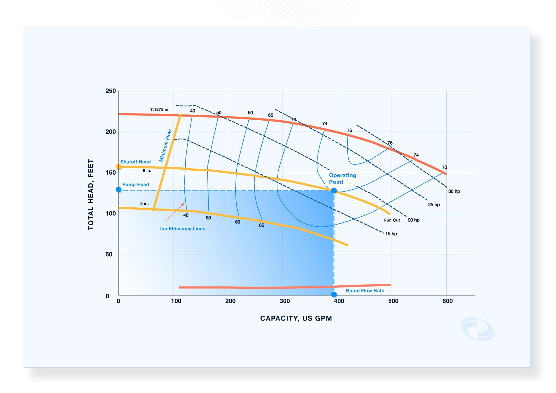 Figure 1: Example of Pump Performance Curve
The pump's performance curve, also known as the head capacity curve, is established by carrying out empirical tests on the pump, following manufacturing standards. The resulting data on head and flow rate is refined to create a smooth curve. The manufacturer of the pump can be asked to provide either a performance curve for a specific impeller size and speed or multiple curves for various impeller sizes or speeds.
Typically, as the flow rate of fluid increases, the pump head decreases. This is because higher volumetric flow rates lead to increased frictional losses in the system. These losses occur as the fluid moves through pipes, fittings, and valves from the source equipment to the pump and from the pump to the destination equipment, resulting in a reduction in the total head produced.
Factors Affecting Pump Curve Selection
At the minimum, the items below influence whether a pump curve will fit to your system:
- Shut-Off Head or resulting pump shutoff pressure
- Head Rise to shutoff or pump curve slope
- Best Efficiency Point (BEP)
- Margin between available (NPSHA) and manufacturer required Net Positive Suction Head (NPSHR)
More details on these factors can be found on this blog - How to check centrifugal pump curve fit using FluidFlow.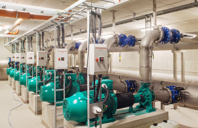
Figure 2: Selecting the best pump for your system not only makes your system safer and more efficient. It also improves a pump’s availability and reliability thereby ensuring operating requirements are always met.
Learning how to read pump curves is an essential step in ensuring that a pump will achieve optimum performance under safe conditions. Understanding key information on pump curves and knowing the factors that affect pump curve selection can ensure that the best pump is selected for fluid systems.
Related Articles:
Centrifugal Pump Performance Curve Explained
How to Check Pump Curve Fit using FluidFlow
.